3D Printed Sword
Contents
After completing my Ender3 S1 Pro upgrades, it was time to truly put the printer to the test. With Klipper running fast and stable, large-format builds suddenly became practical, and this project quickly turned into the ultimate stress test.
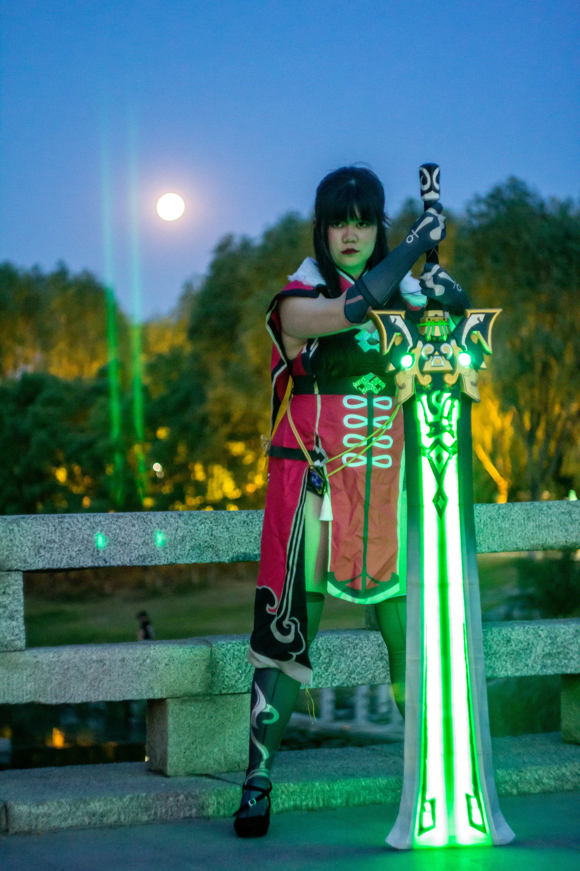
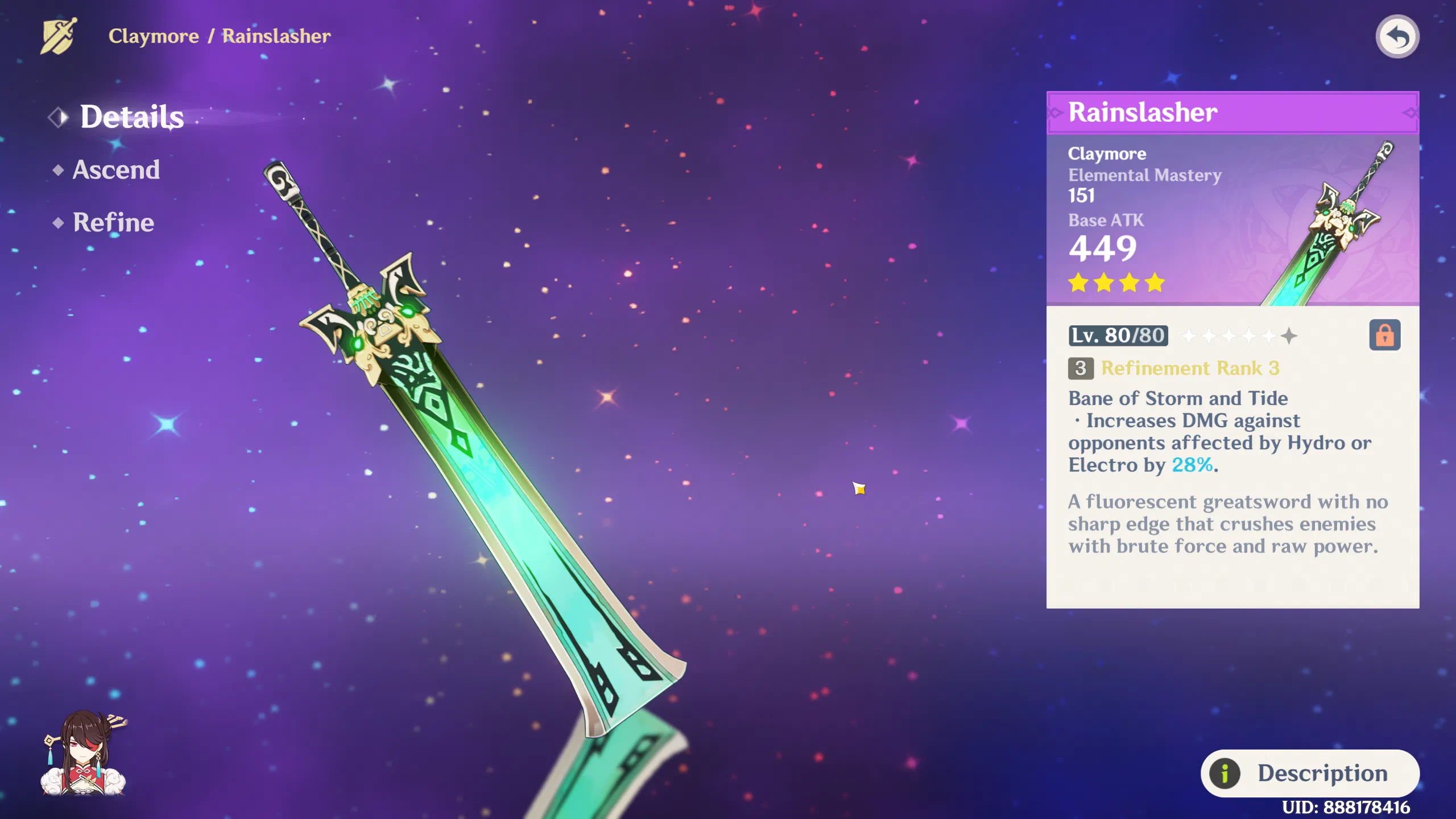
As a long-time Genshin Impact player and fan, I started wondering if some of the in-game swords could be recreated physically. With my favourite character, the pirate Beidou, wielding a 1.70m claymore as one of her signature weapons, there was really only one answer: build the Rainslasher in real life, at full scale.



Of course, this would not be simple. From CAD design and structural planning to electronics, printing, assembly, and paint, this became a multi-month project.
Rainslasher Concept
I began by closely studying the base weapon design, using renders by Ana Figueiredo:
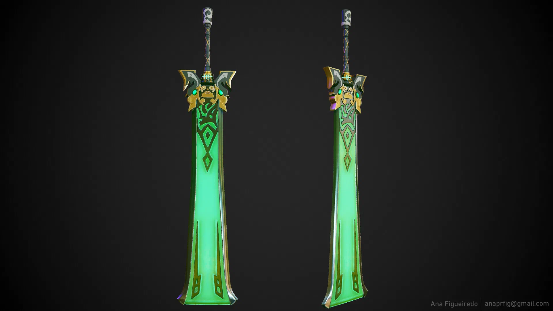
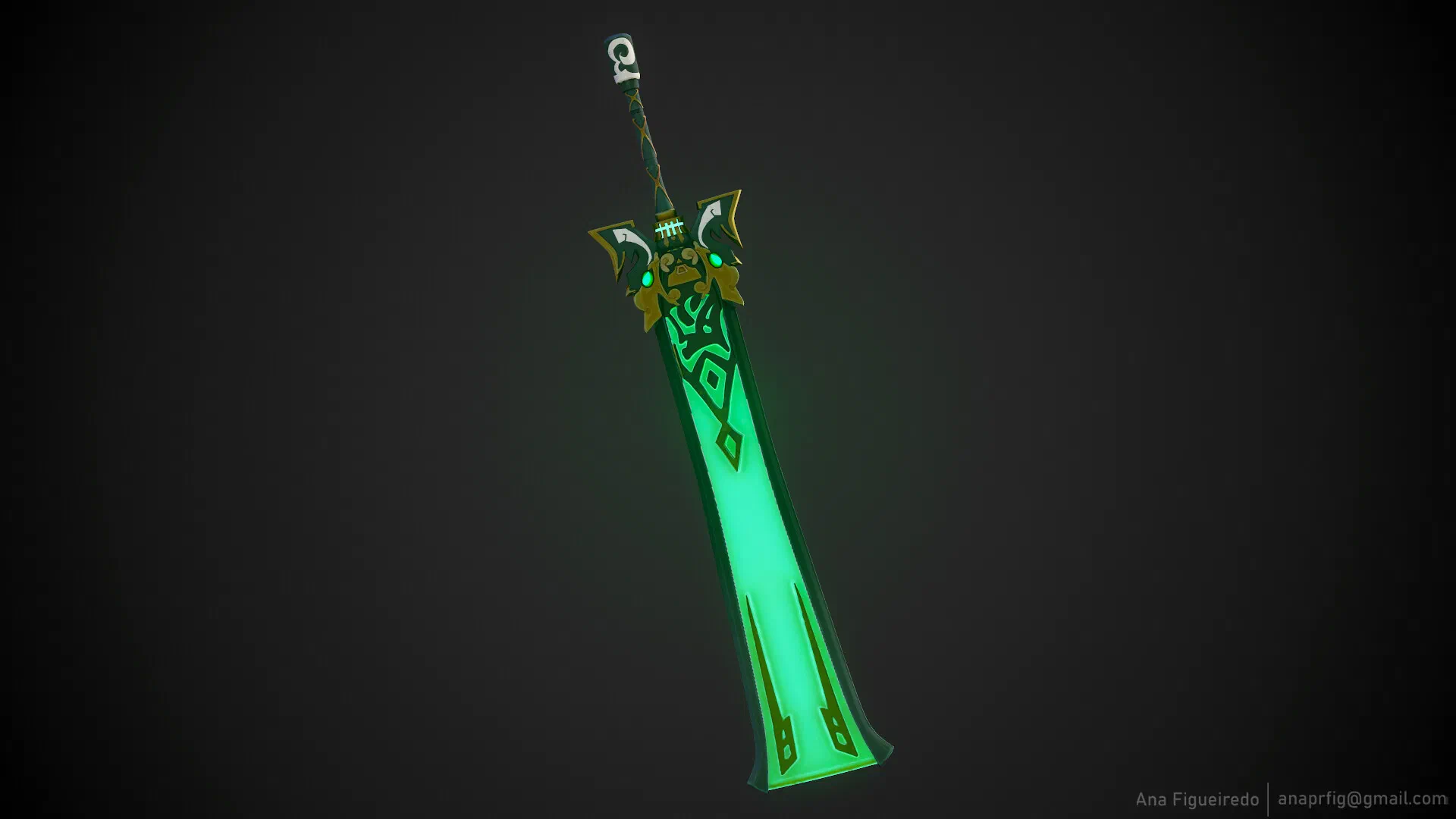
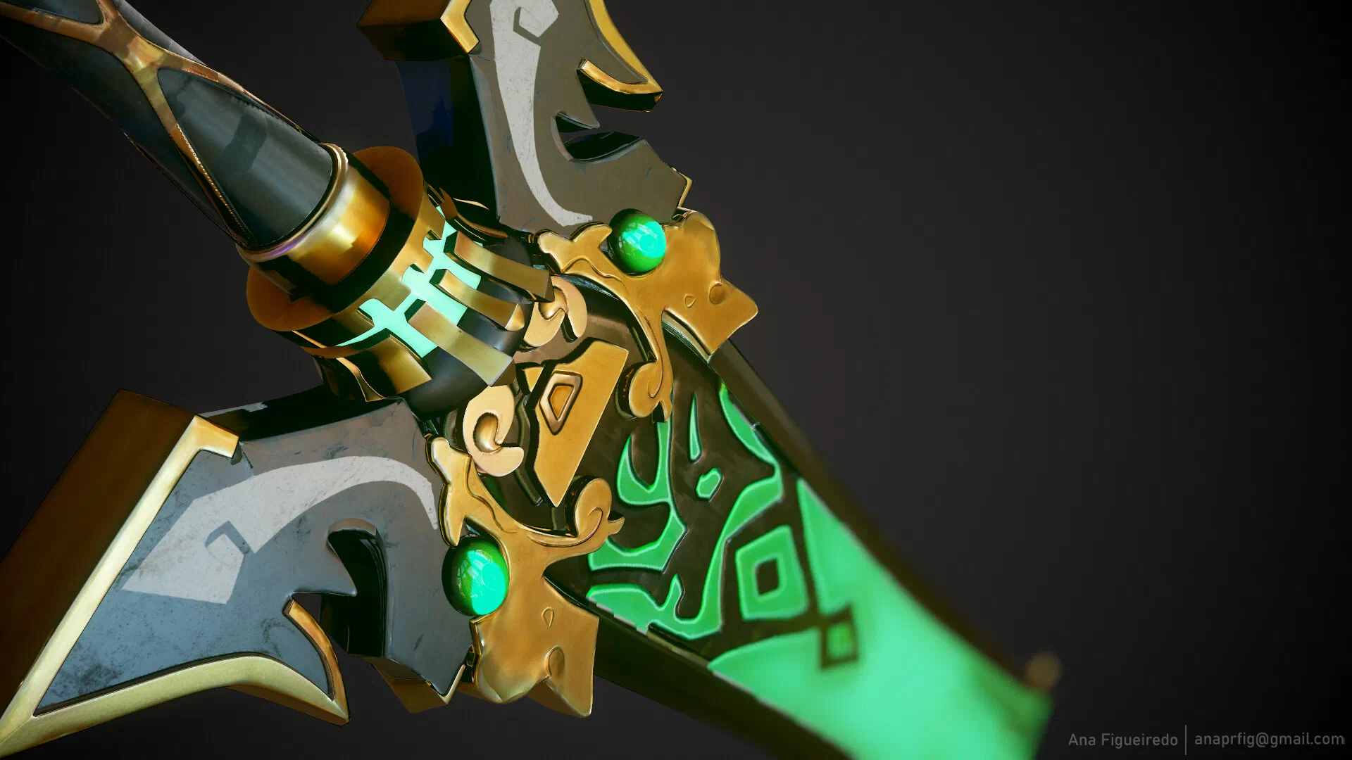
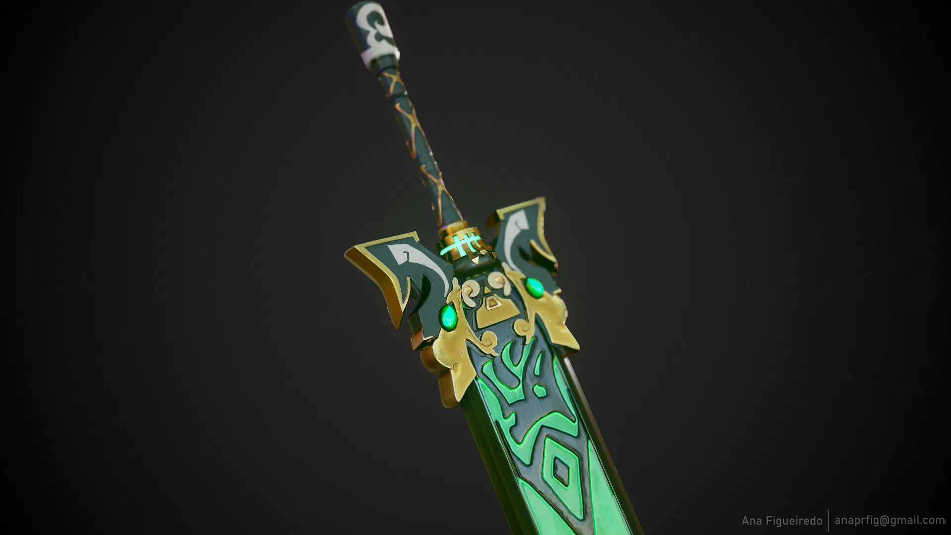
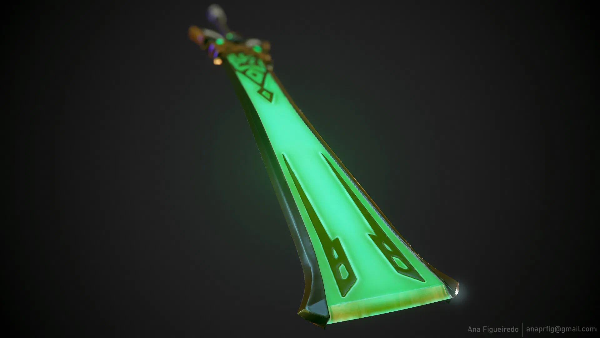
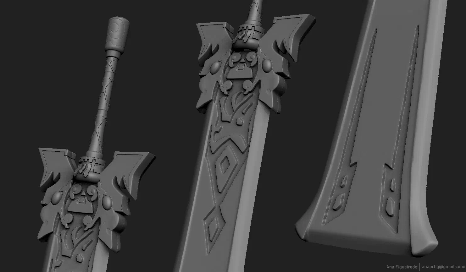
The sword design is striking: an outward-slanting blade profile, an ornate cross-guard with dragon-eye motifs, and a vivid green glowing core. It looks elegant in-game, but mechanically it presents several real-world constraints.
Using a mix of colored plastics, felt and rope wrapping, plus hand-painted details, I started translating that visual design into CAD geometry.
CAD Work
After importing game-extracted 3D files into CAD, the sheer scale became obvious. At 1.70m long, and only around 3cm wide at the thinnest part of the handle, a fully plastic structure would not have sufficient rigidity.
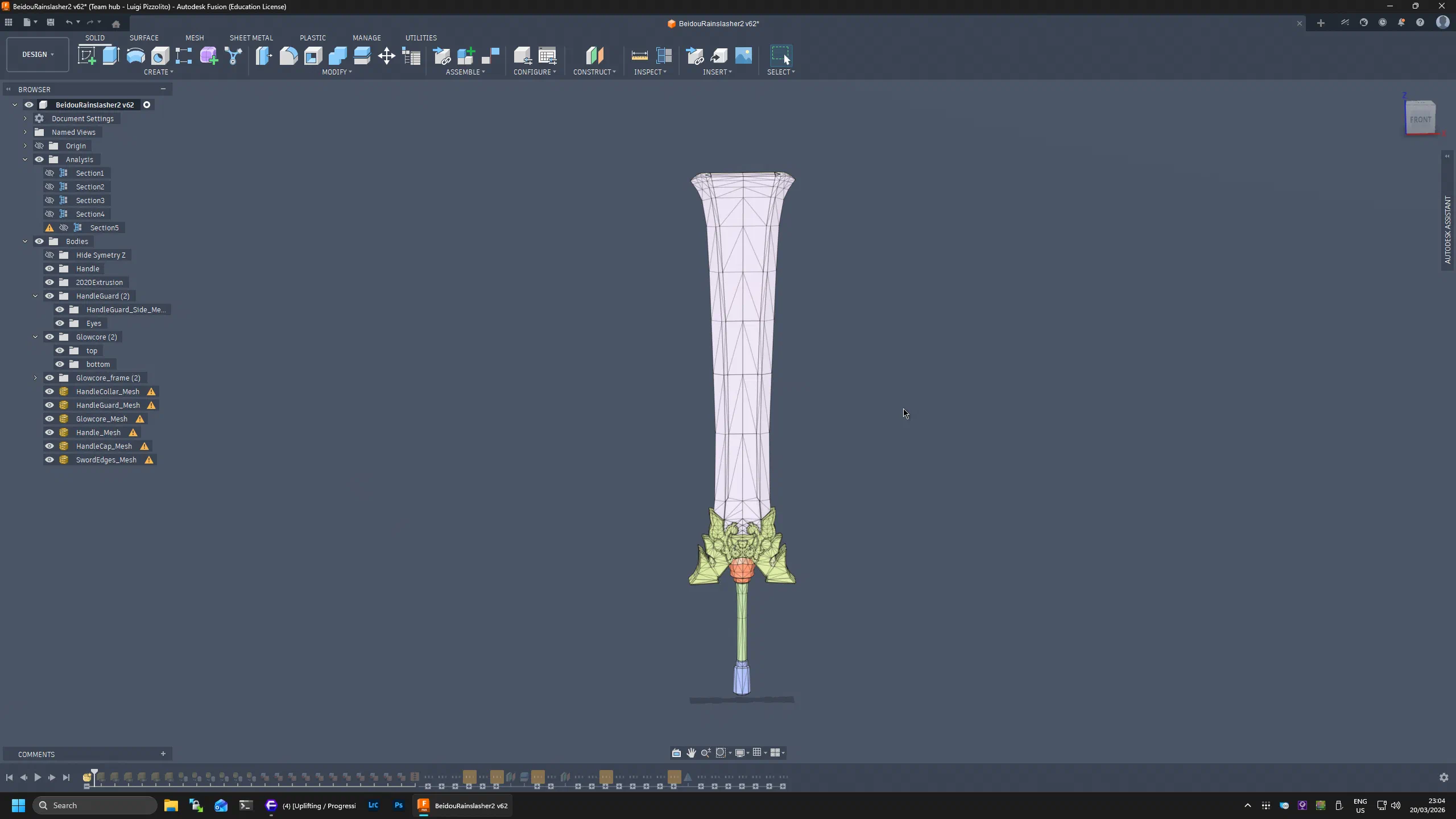
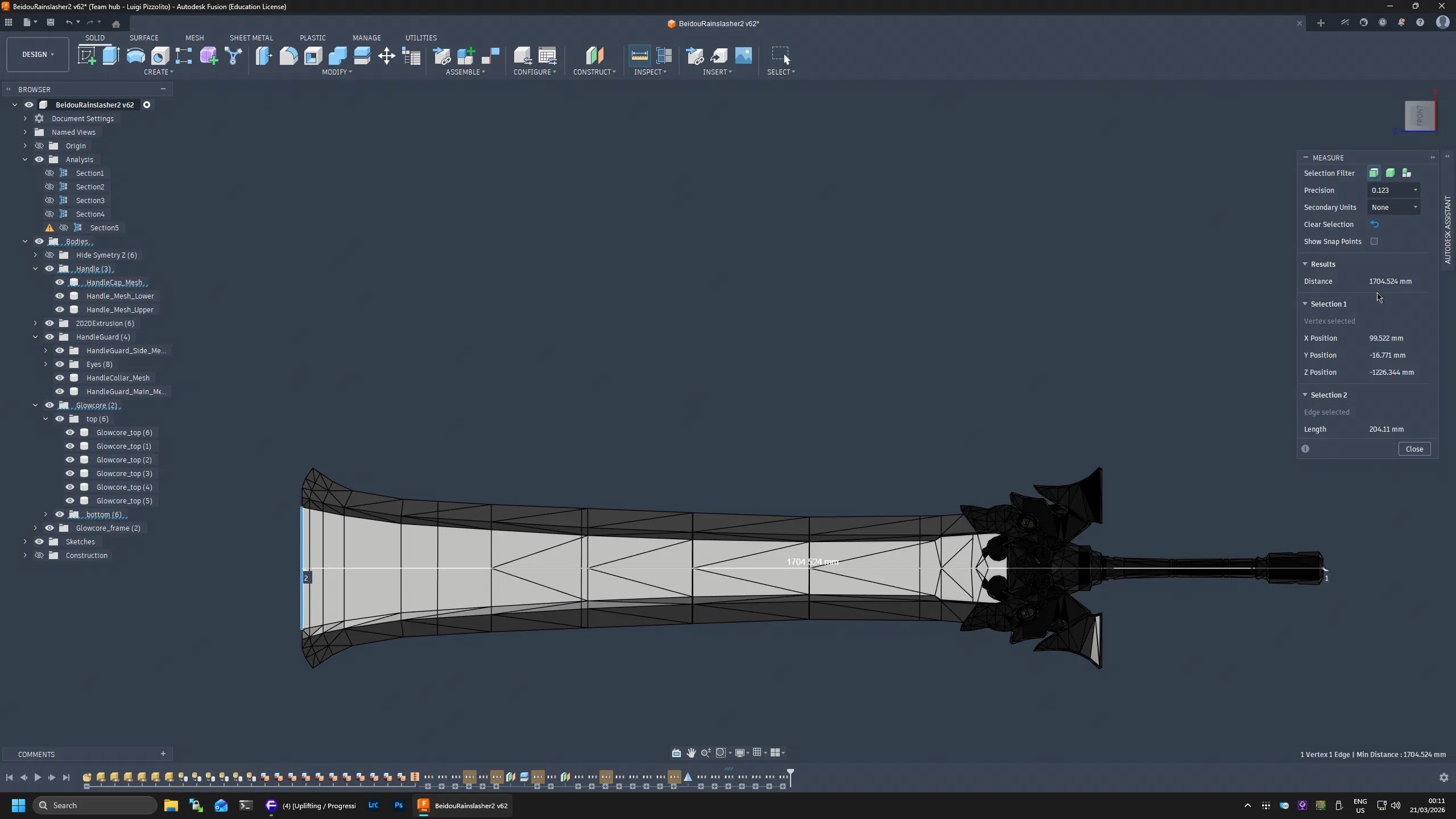
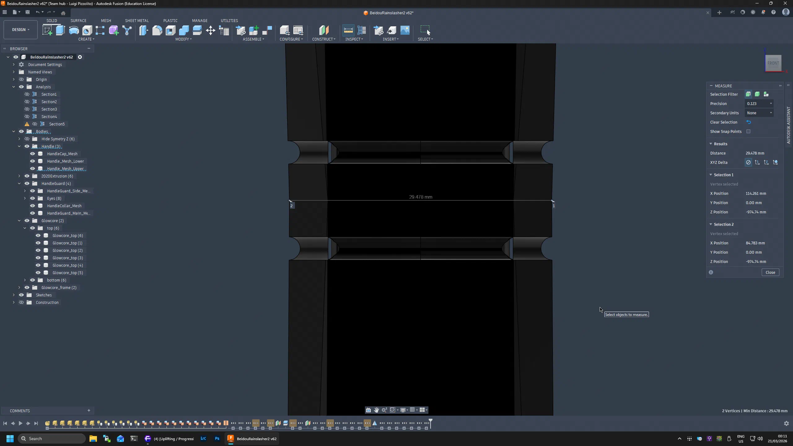
A quick Fusion 360 volume estimate suggested the final print would consume about 4-5kg of PLA. That led to the first major design decision: use a 1.65m 2020 aluminum extrusion as the internal backbone.
This solved multiple problems at once: strong central structure for full-length stiffness, low-cost and easy to source, T-slot mounting points on all four sides, and a center channel for wire routing.
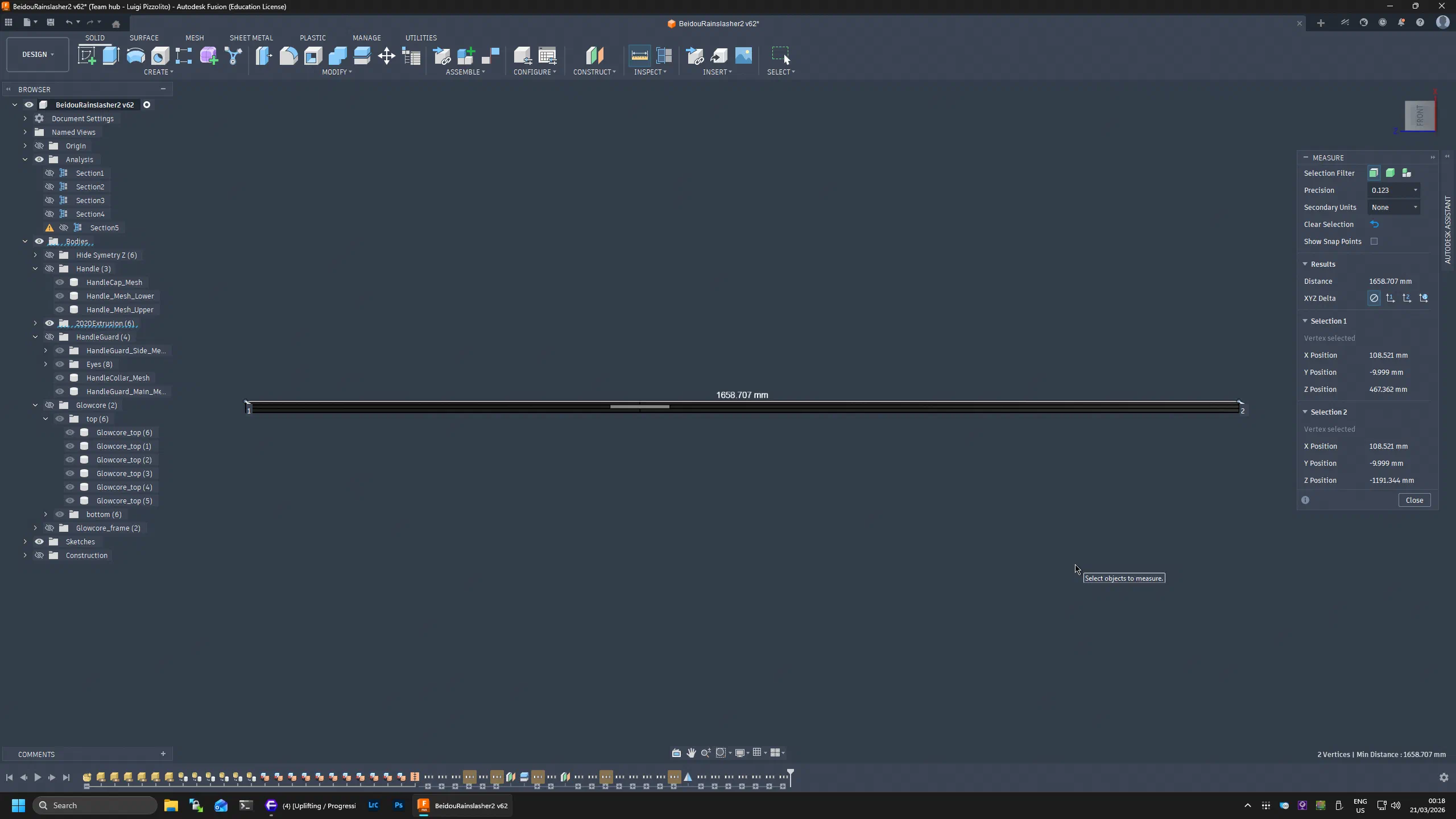
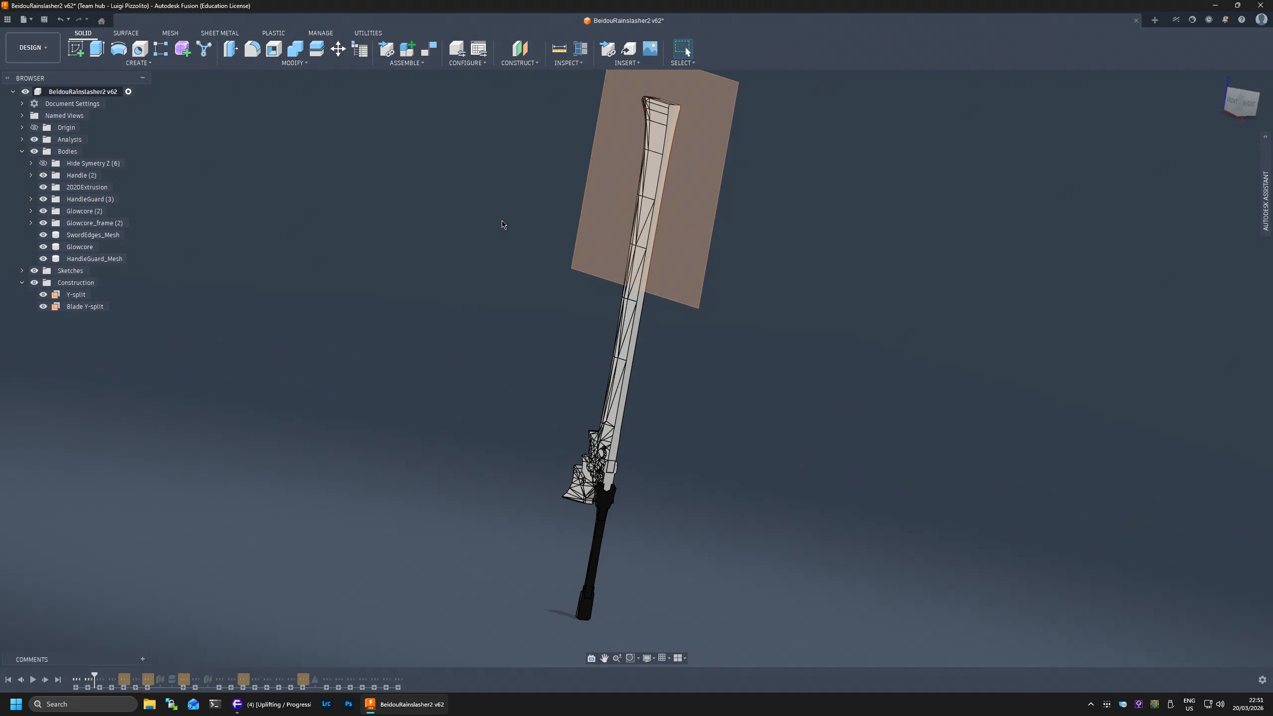
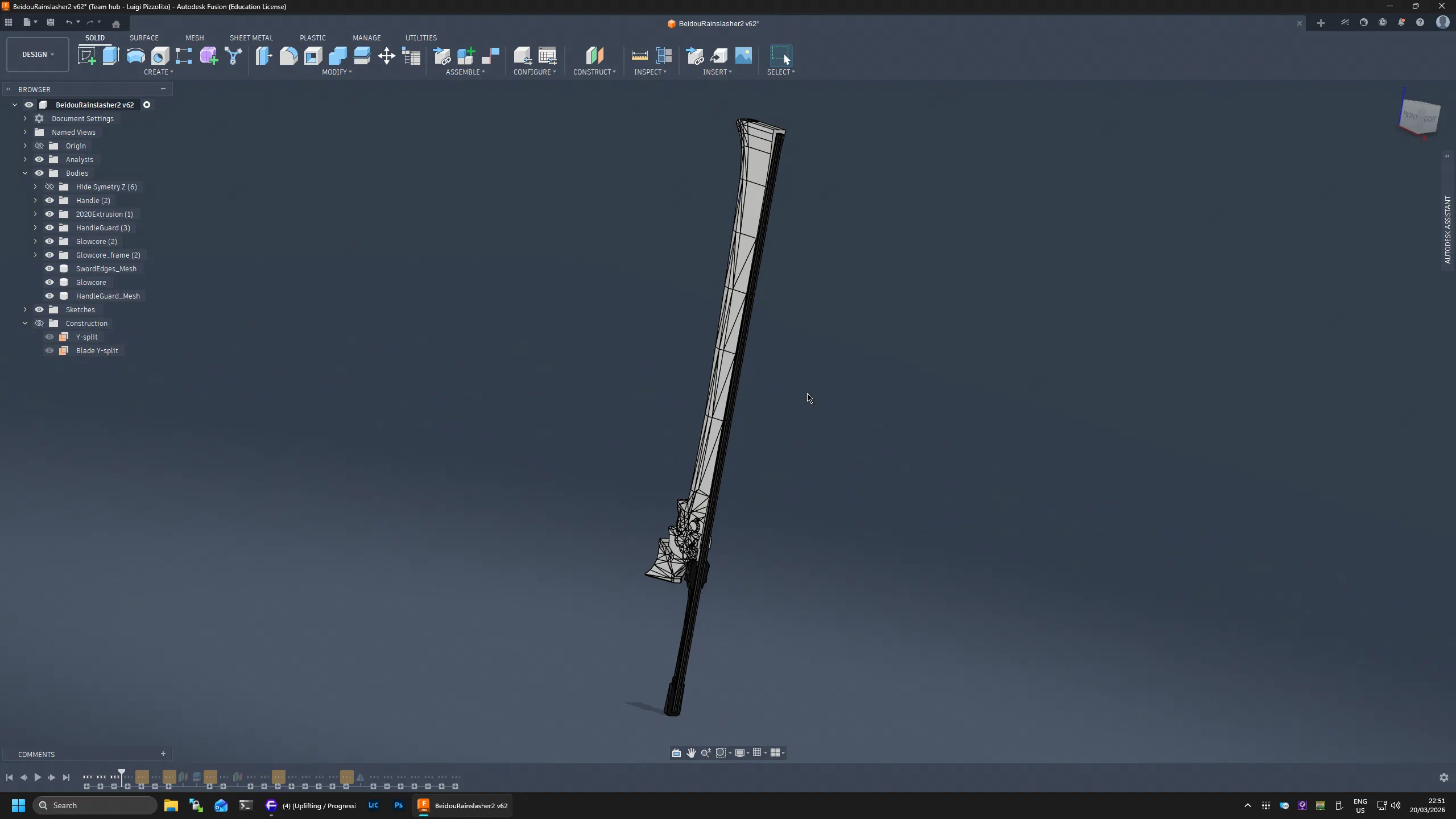
With that in mind, I modeled the backbone as a 1.0m and 0.65m joined section running through almost the entire sword:
Splicing and Channel Routing
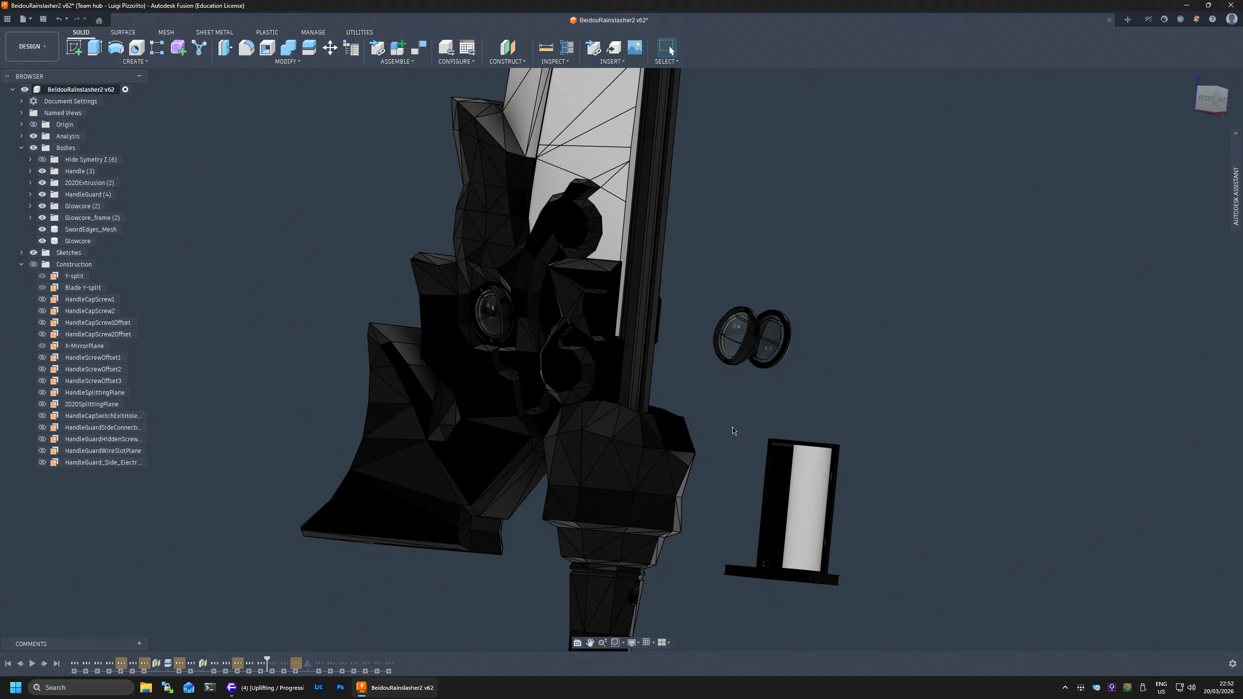
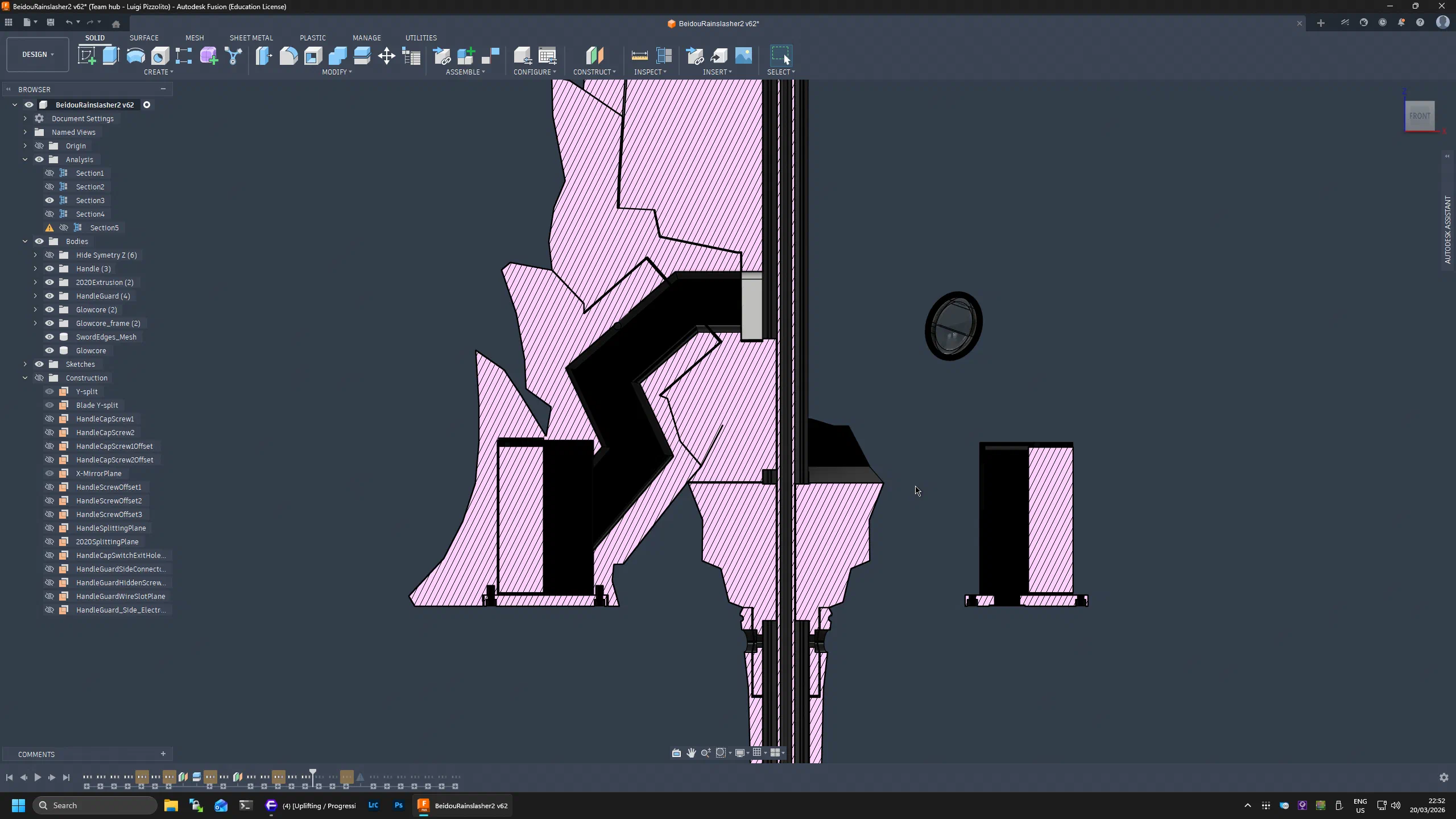
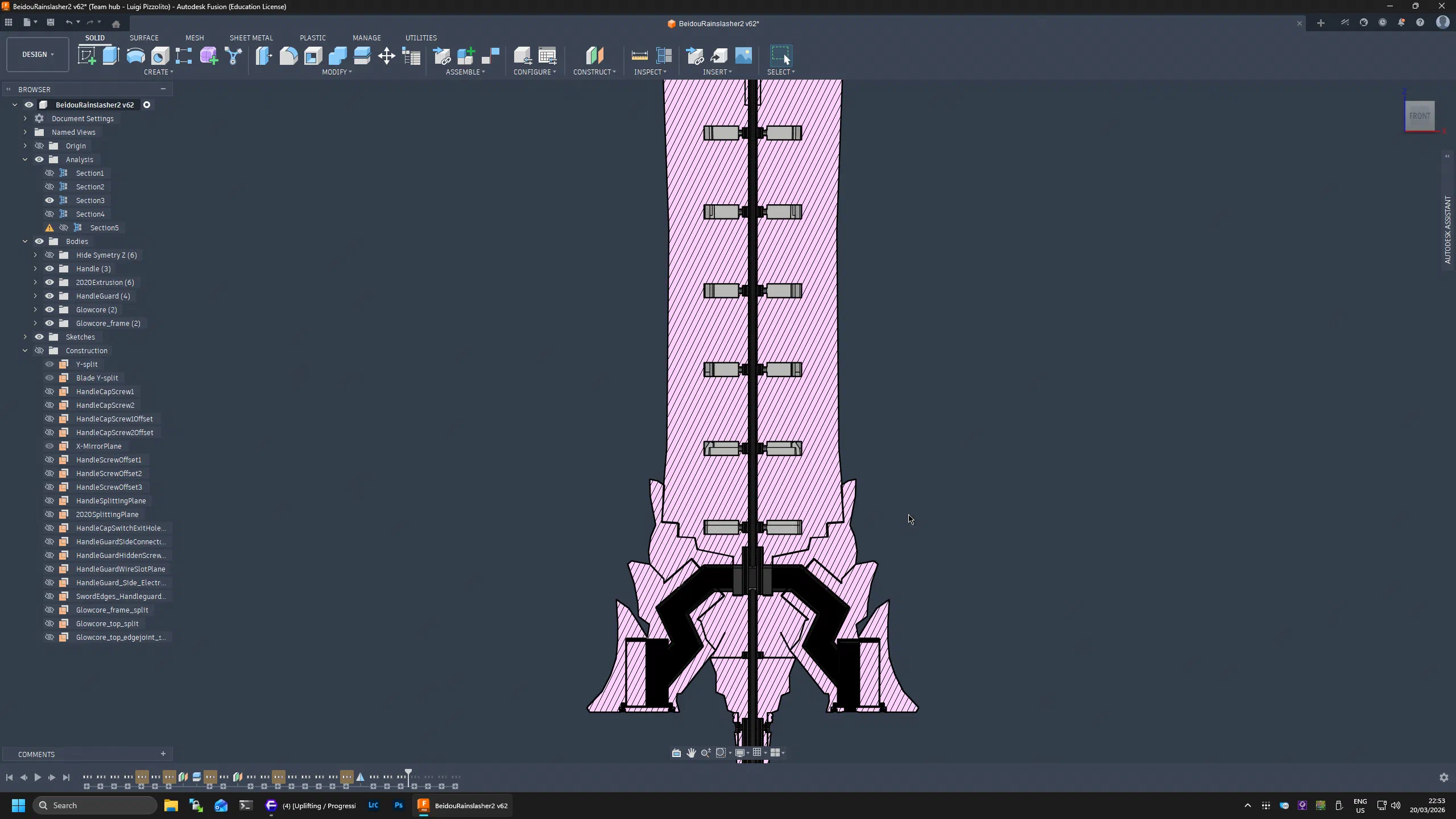
The next phase was a very careful and fairly tedious segmentation process: splitting the model into printable sections while preserving all internal routing paths for wiring and electronics.
The final design includes two electronics drawers integrated into the cross-guard, each containing one 18650 lithium-ion cell and associated control/driver electronics. Separate channels were included for the dragon-eye LEDs and for the main blade glow path.
Blade Core Design
One of the trickiest parts was the blade layering strategy. The blade has a concave profile: the center narrows while both base and tip flare wider. That geometry introduces assembly constraints when all parts must slide along a fixed central extrusion.
Because of this, parts above the center constriction must be assembled from one direction, and parts below from the other, otherwise interference makes assembly impossible.
To preserve the two-tone blade look, the glowing core had to be a separate set of sliding parts. In practice, each section became a four-part stack that uses all four T-slots of the 2020 extrusion.
That is easier to understand in cross-section:
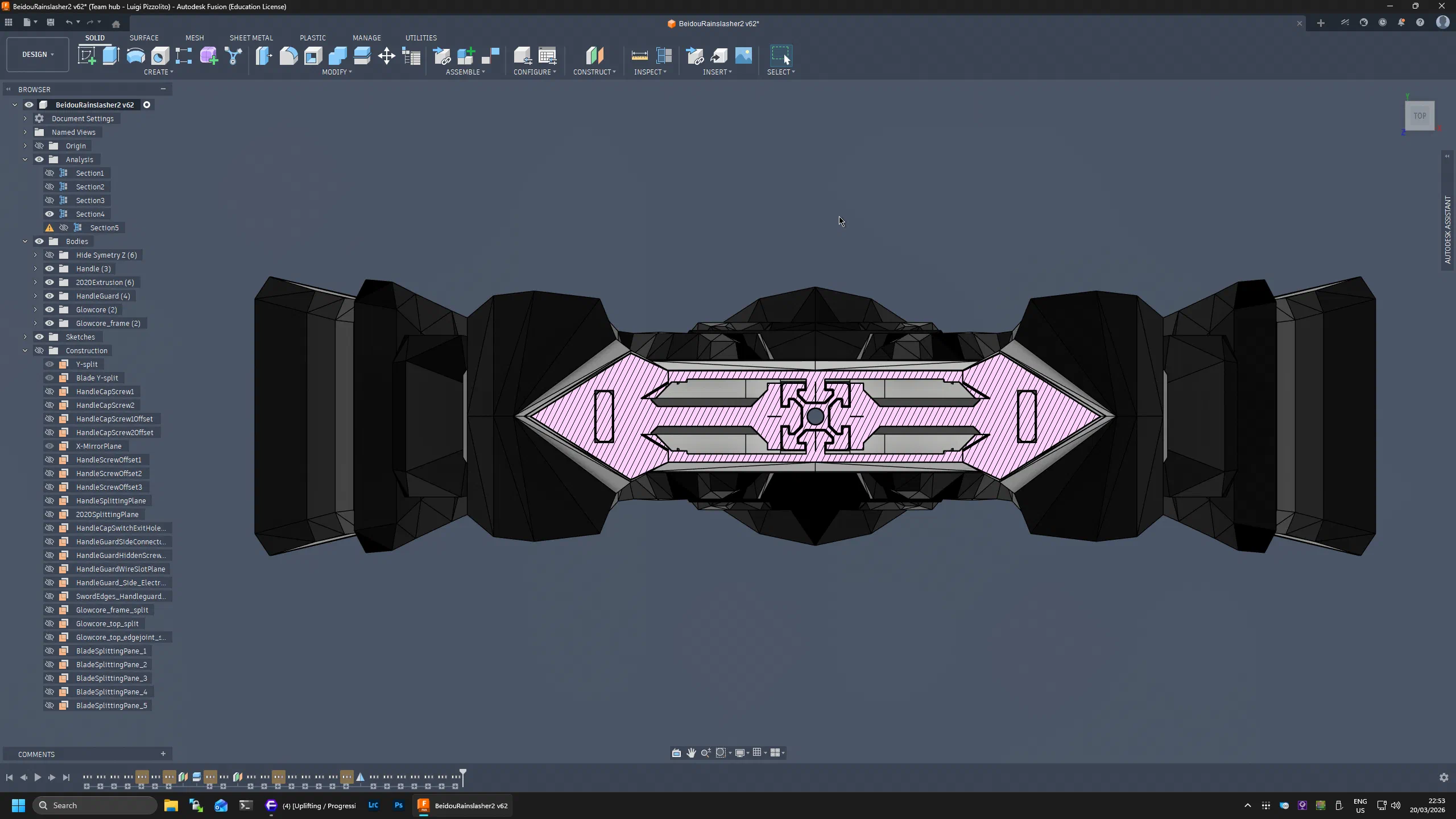
The outer edge parts serve double duty: they define the blade edge and also form channels where LED strips sit to illuminate the core. Great conceptually, but difficult to execute with the concave profile, because the interlocks and clearances must remain consistent across a complex 3D path.
A Tricky 3D Spline
With a combination of construction planes and offset surfaces in Fusion 360, I built a 3D spline path that followed the blade geometry while maintaining enough tolerance for the center panels to slide and lock.
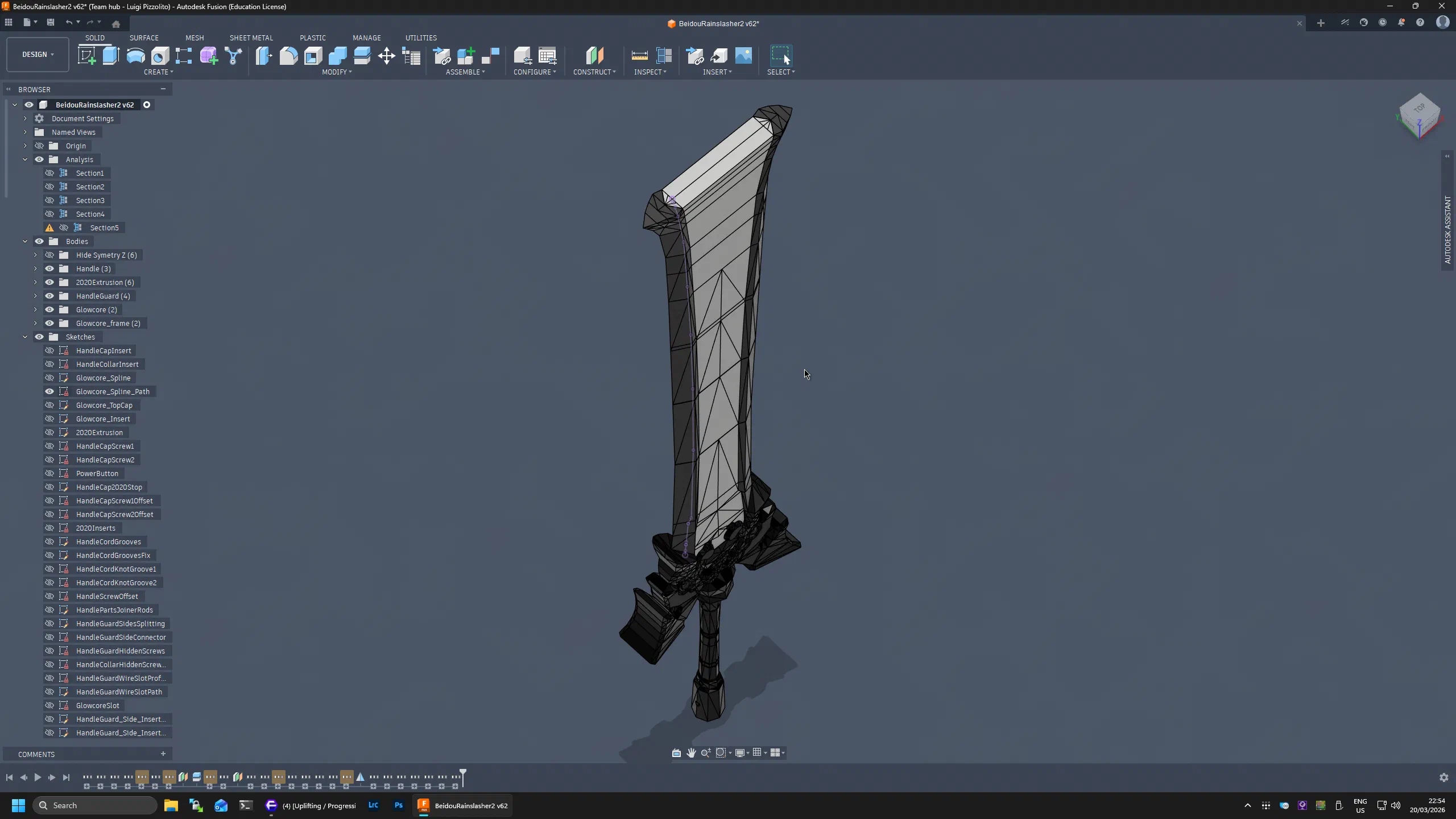
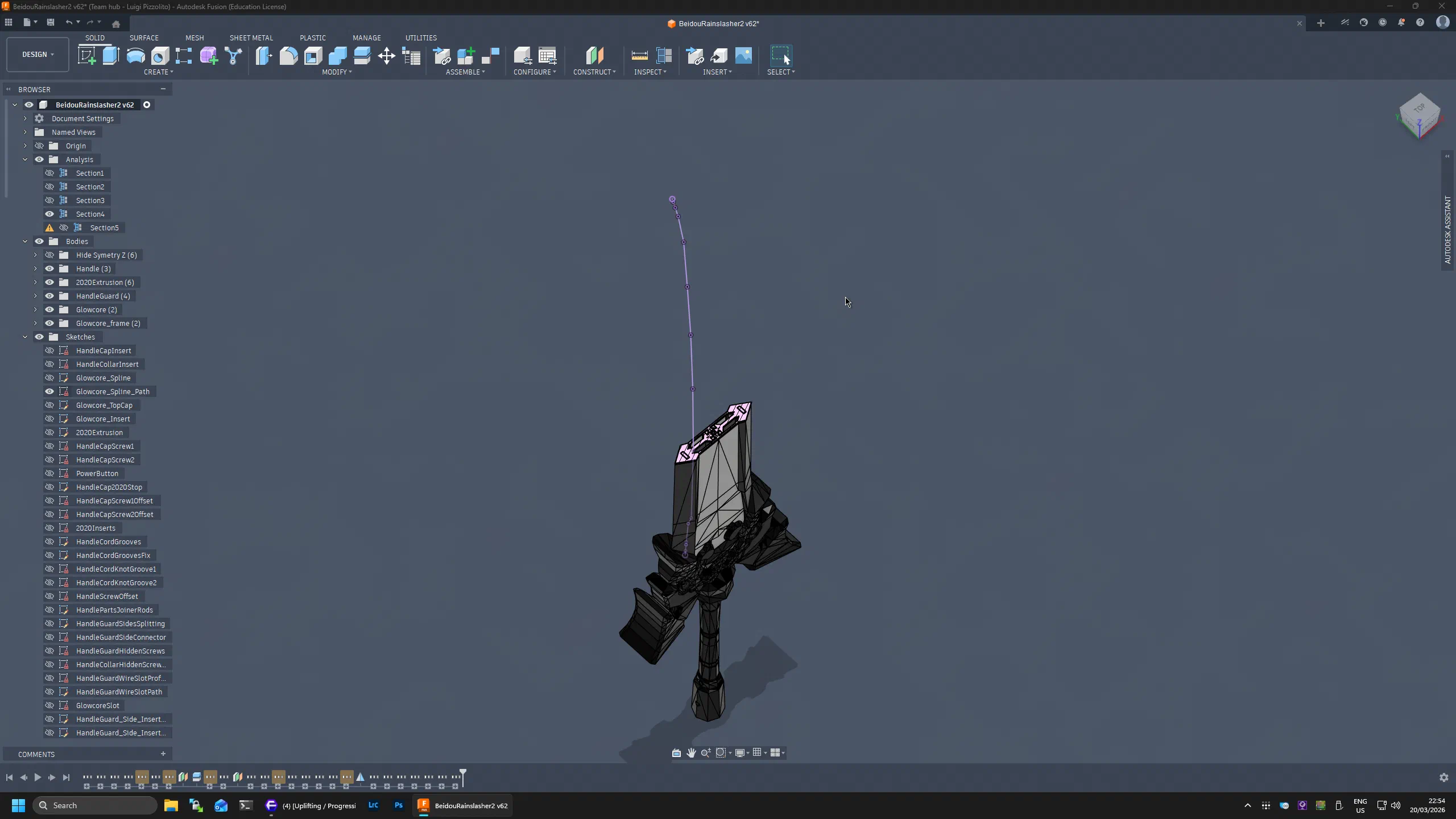
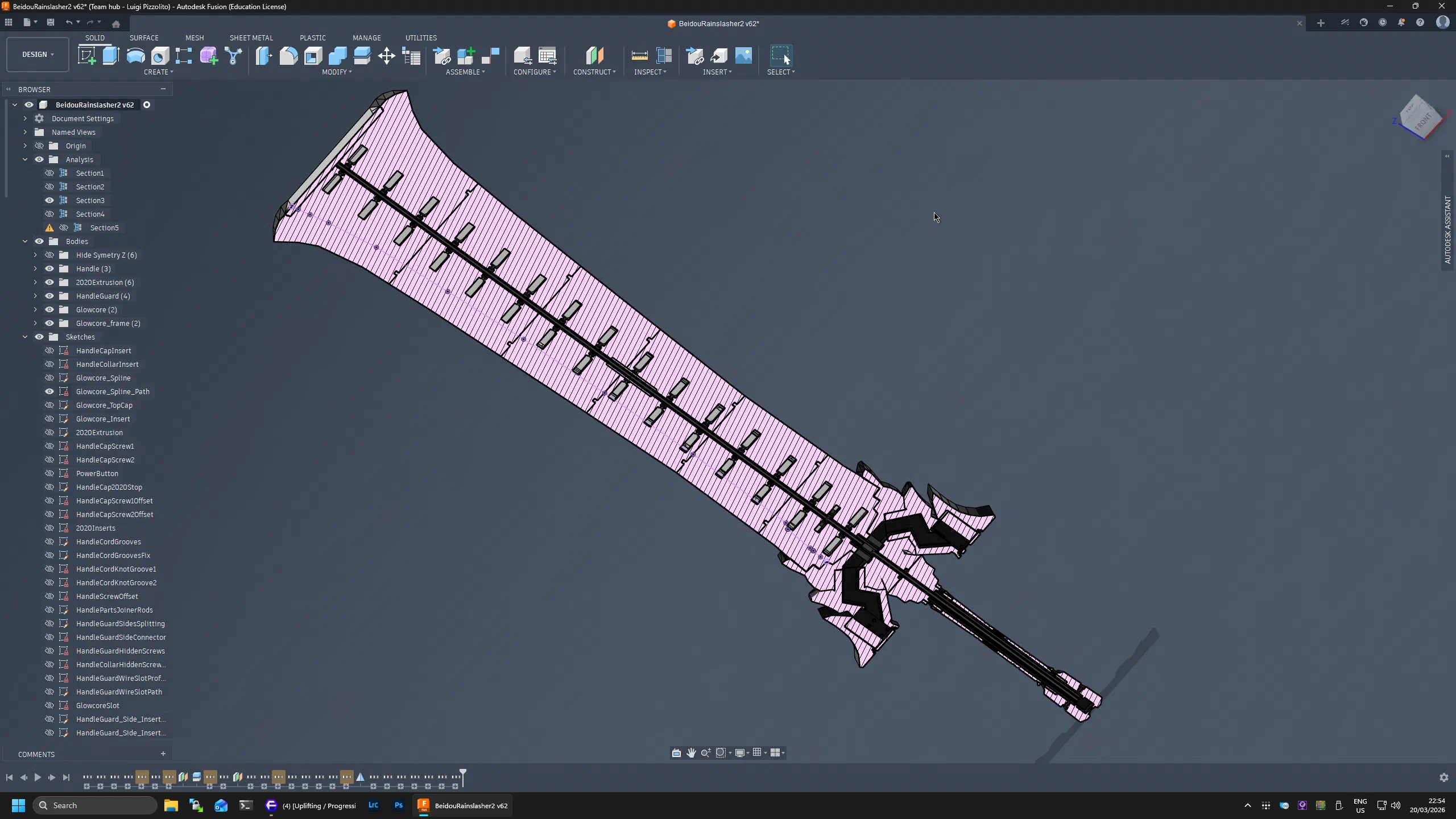
This ended up being the most time-consuming CAD step. Many iterations were needed to check fit, clearances, and interference across all four interlocking components.
Splitting Parts for 3D Printing
Once the geometry and tolerances were stable, the remaining CAD task was production splitting. Large pieces were divided to fit the Ender3 S1 Pro build volume (220x220x270mm).
Most cuts were straightforward planar sections along the blade. The cross-guard needed more complex cuts, including keyed insert geometry to maintain accurate alignment and stiffness near the first blade section.
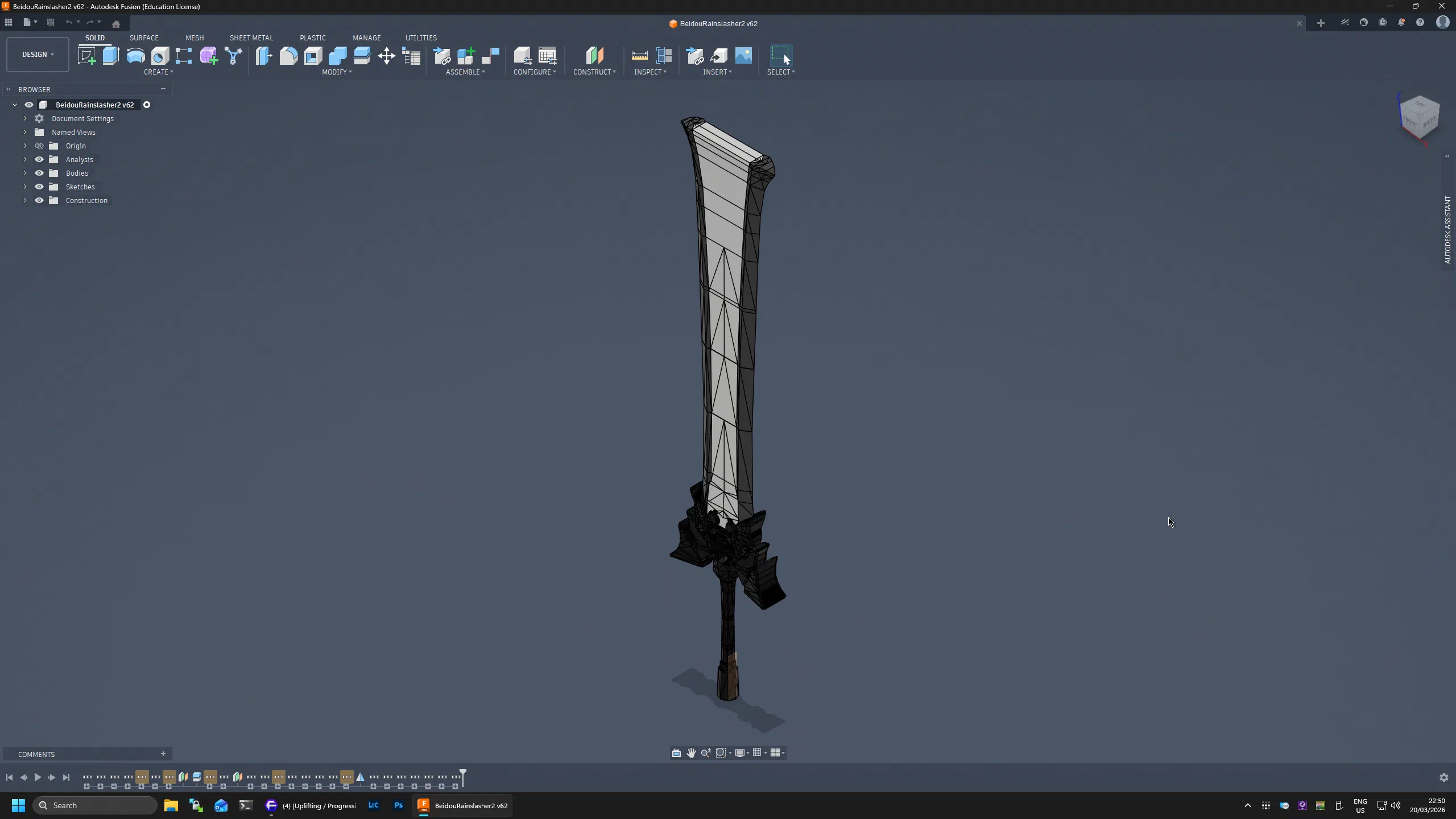
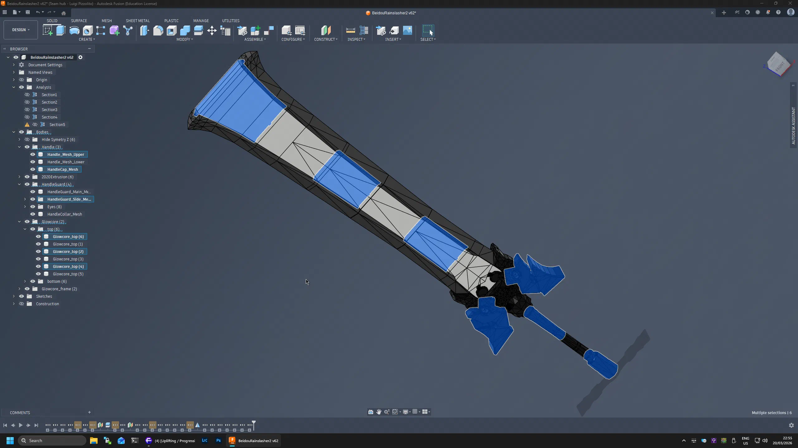
Even with aggressive splitting, the scale still felt enormous: sections around 20cm tall still required more than eight major segments to span the full sword length.
After nearly a full month of CAD work (November to December), every part was finalized and interference-checked.
UV Fluoresence Calibration
One key aesthetic goal was reproducing the blade’s glowing look. While evaluating materials, I found fluorescent neon green PLA, which glows very strongly under UV light.
However, I also wanted a shimmer animation using PWM control, and that raised two practical questions: what panel thickness gives the best backlit glow, and what is the fluorescence decay response after UV excitation is reduced?
When illuminated from the front, the glow looked excellent:
Back-lighting behaved differently, so I printed a stepped-thickness sample to calibrate transmitted glow:
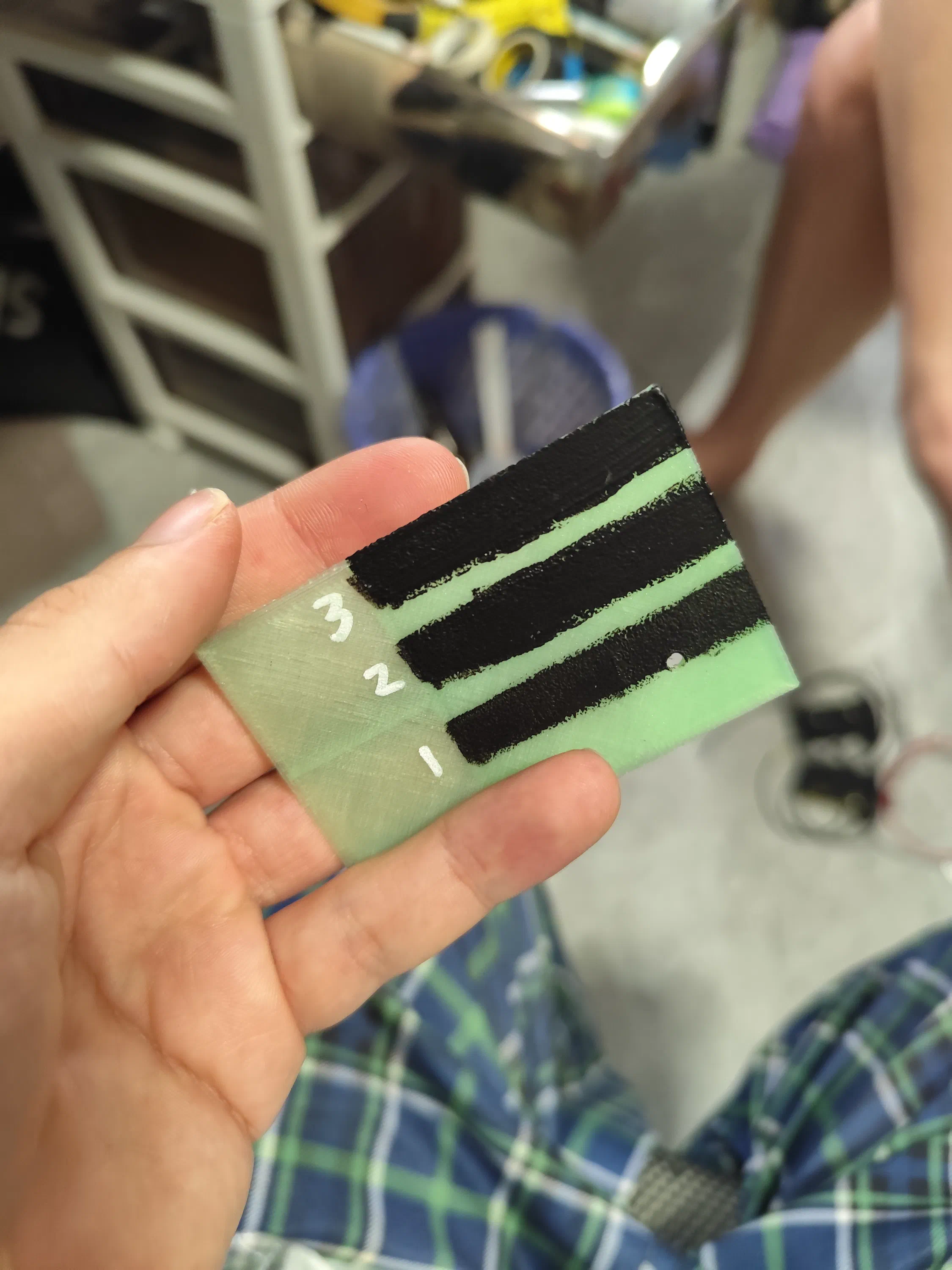
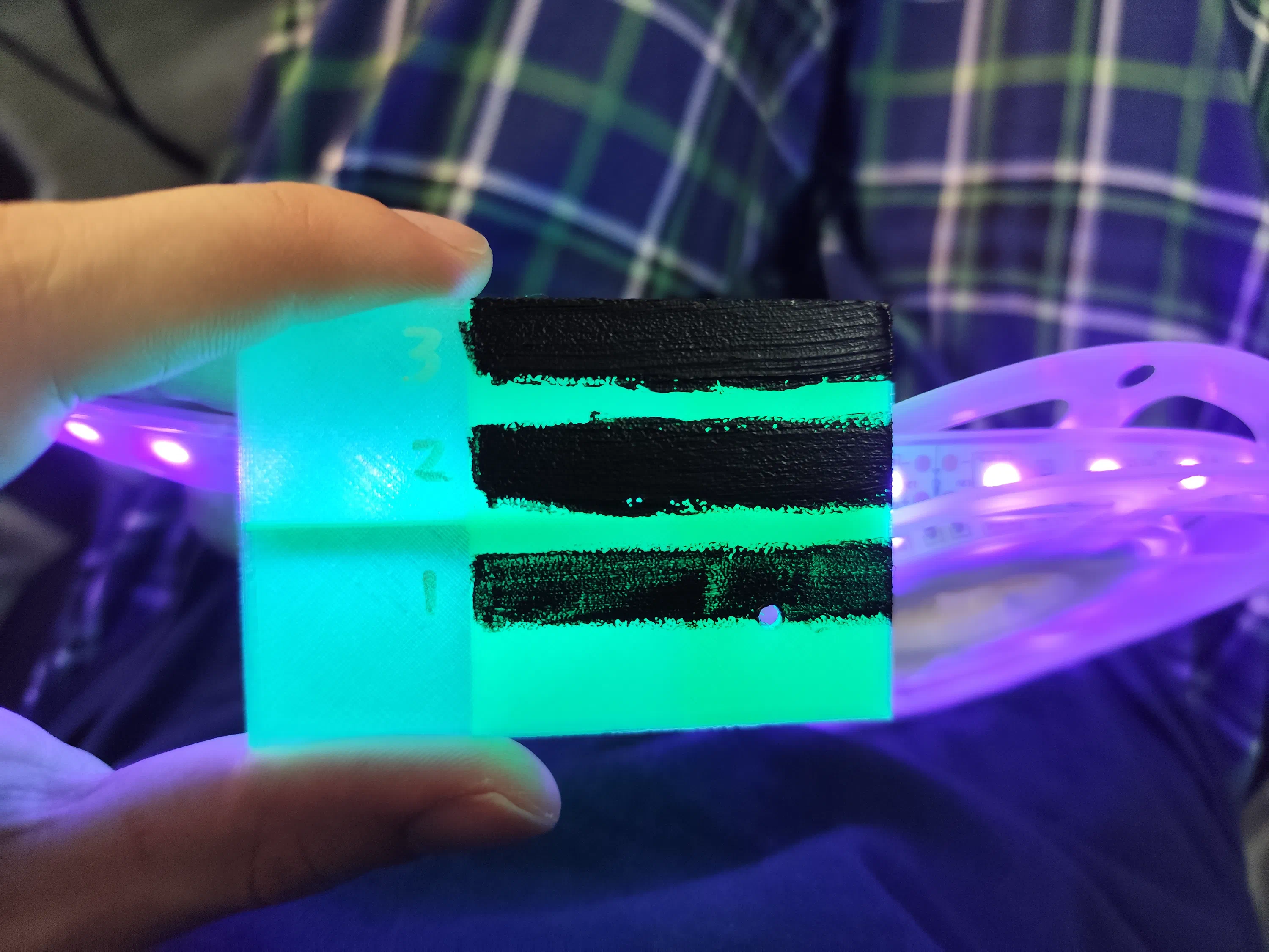
This quickly showed ~2.5mm to be a good compromise: bright enough under UV, while still allowing black paint details to mask lower regions without excessive bleed-through.
The second question was temporal response. Fluorescent materials do not stop emitting immediately after UV drops; they decay over time. The decay roughly follows an exponential profile, which can be modeled and used to tune PWM duty behavior for both visual smoothness and potential power savings.
Software
Using the test coupon (with the drilled hole shown above), I mounted a TEMT6000 I2C lux sensor directly against the part. An Arduino sketch captured response data, which I exported as CSV and fit in MATLAB to estimate decay constants.
From there, I implemented C++ firmware for an ATtiny85 board. The shimmer output combines a baseline brightness term with a sinusoidal component, then drives MOSFET stages via PWM to control UV strips powered by 12V boost converters.
To create a more interesting pattern, I decided to simulate a heart beat instead of a plain sine wave modulation. This was done using a bool variable to switch between the diastole and systole pulse phases, with the smaller phase being applied with a reduction multiplier. Another detail is the change of the modulation speed to match a heartbeat as well, as the systole phase is twice as long as the diatole phase. This is all implemented in the simple main loop below:
 1void loop() {
 2    modulationCounter++;
 3
 4    // Update brightness at the end of the modulation interval
 5    if (modulationCounter == modulationInterval) {
 6        // Calculate sine wave value (scale for diastole:systole ratio of 2:3)
 7        uint8_t sineValue = (isSystolePhase)
 8                            ? pgm_read_byte(&sineTable[phaseStep]) * 0.6
 9                            : pgm_read_byte(&sineTable[phaseStep]);
10
11        // Adjust brightness with baseline and current level
12        pwmValue = BASELINE_BRIGHTNESS * 255 + sineValue * (1 - BASELINE_BRIGHTNESS);
13        pwmValue *= brightnessLevels[currentBrightnessIndex];
14
15        // Update phase and check for phase reset
16        phaseStep++;
17        if (phaseStep == 0) {
18            isSystolePhase = !isSystolePhase; // Toggle heartbeat phase
19            // Model diastole:systole duration ratio of 1:2
20            modulationInterval = (isSystolePhase) ? MODULATION_SPEED : 2 * MODULATION_SPEED;
21        }
22
23        modulationCounter = 0; // Reset modulation counter
24    }
25
26    // Output the calculated PWM value to the LED
27    analogWrite(LED_PIN, pwmValue);
28
29    delay(1); // Small delay for smoother transitions
30}
GitHub repo:
The firmware also includes practical extras: startup battery reporting and EEPROM-based cycling through four brightness modes when power is toggled.
3D Printing
Then came the long print phase. Most parts took roughly 8-16 hours each, and I worked progressively from lower handle sections upward through the blade edge segments in matte space-gray PLA.
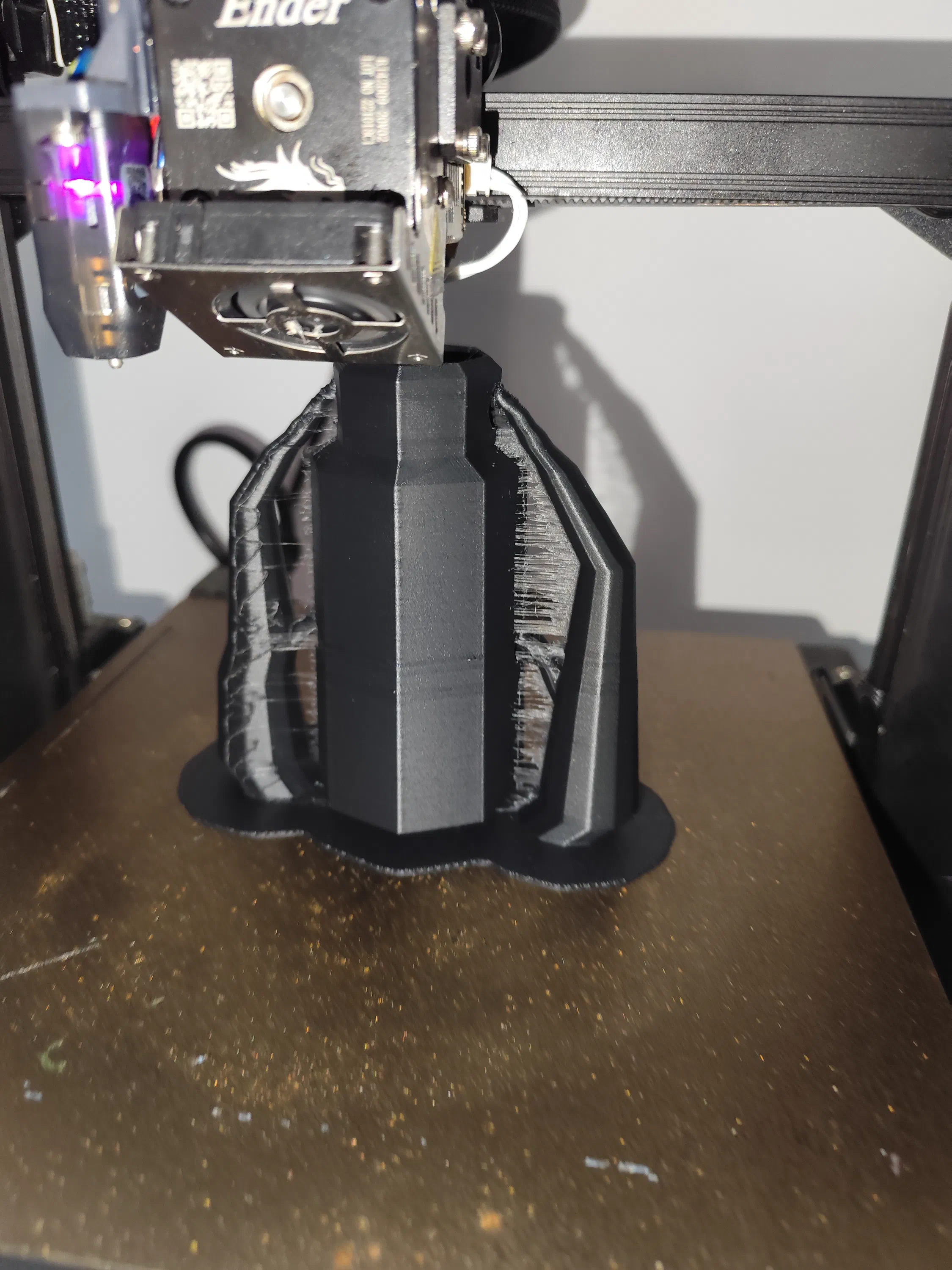
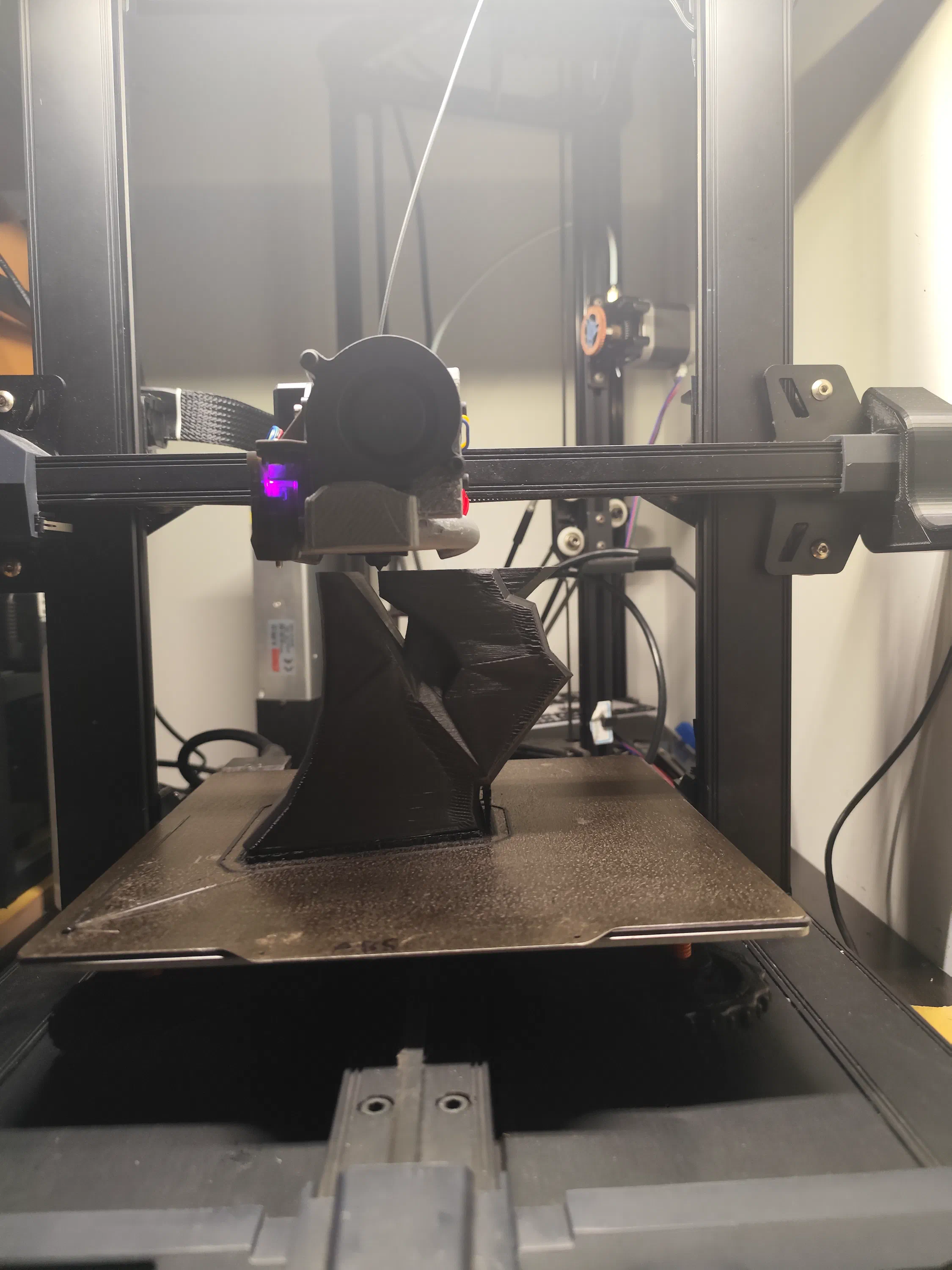
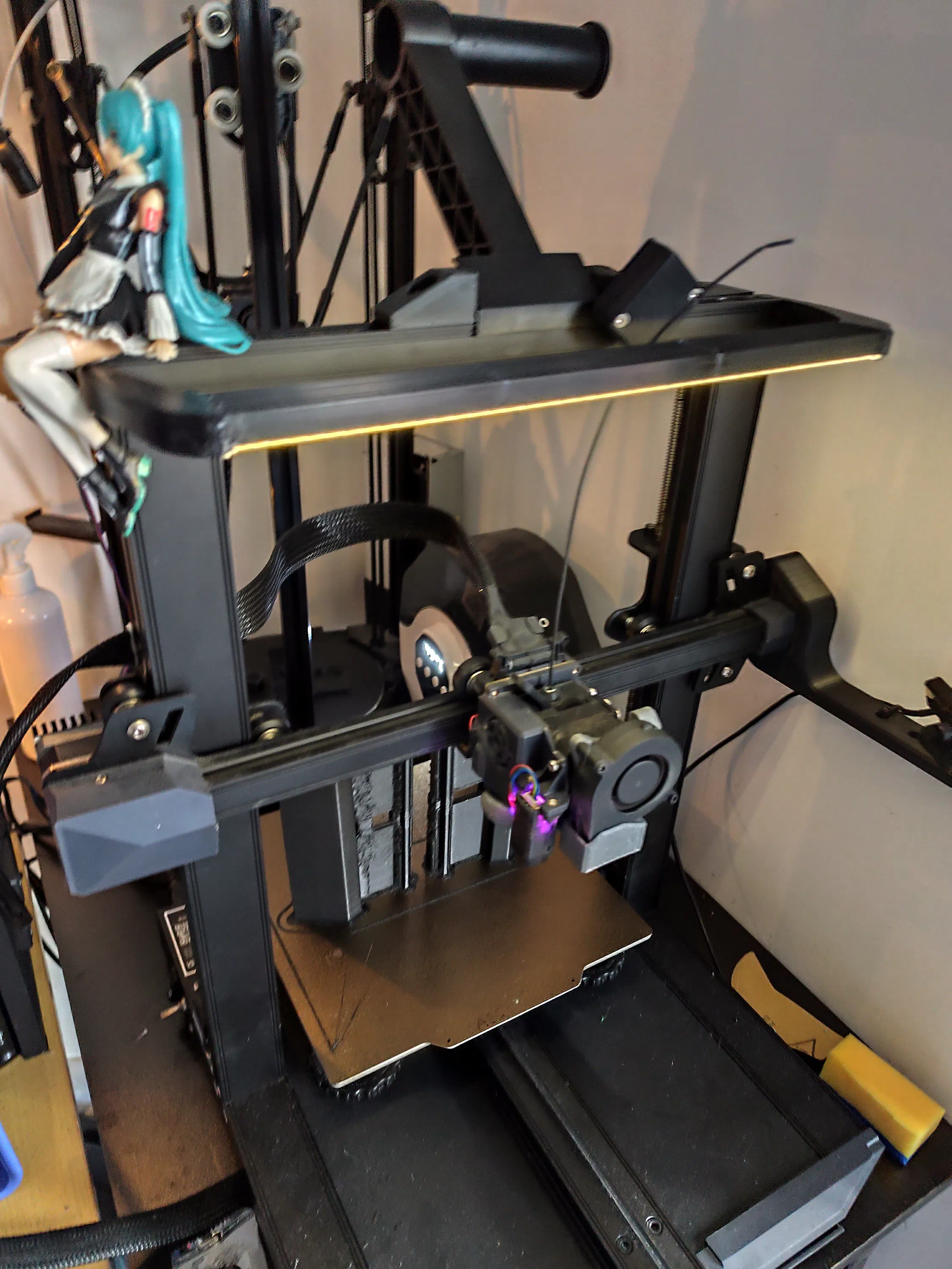
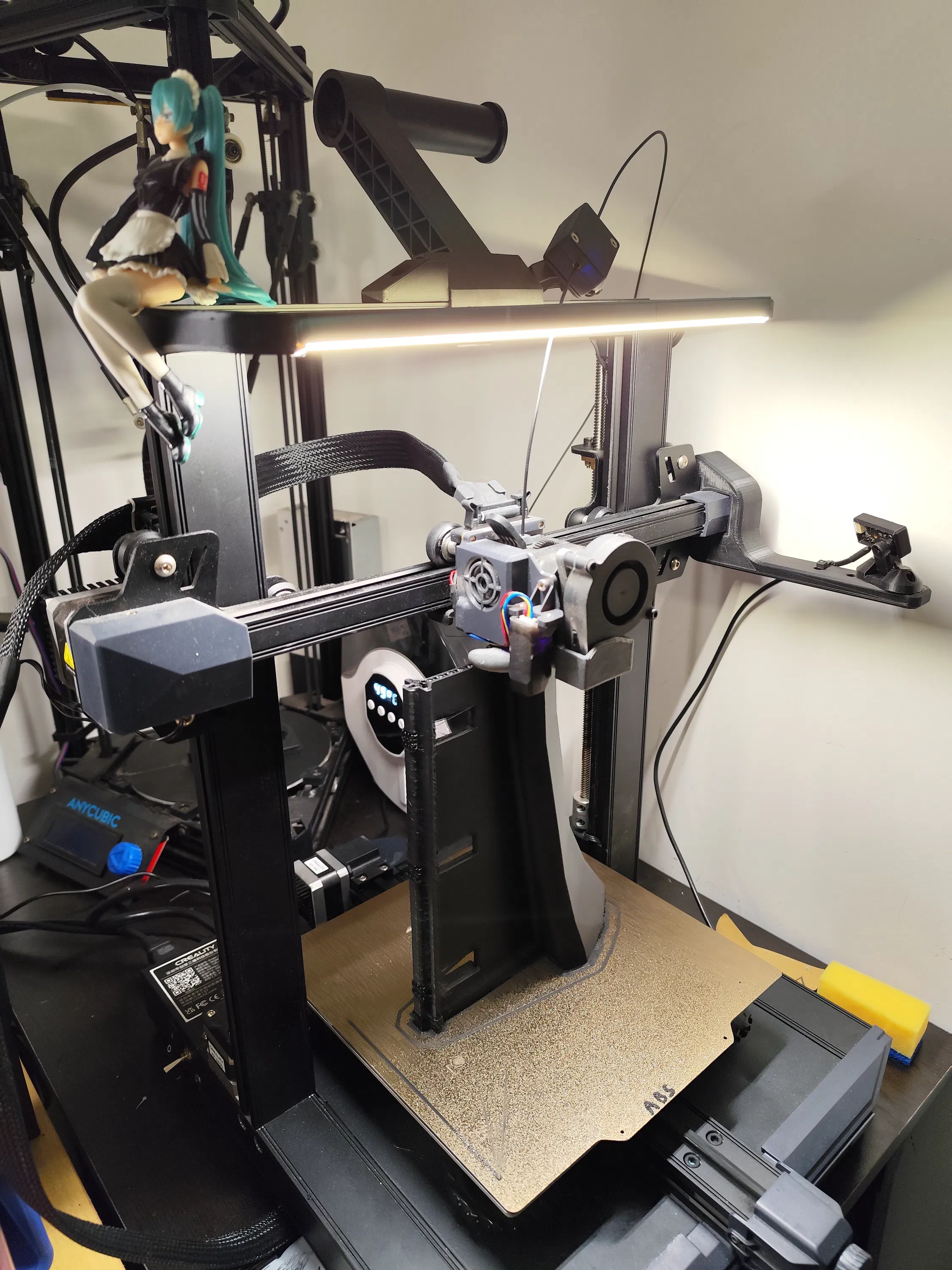
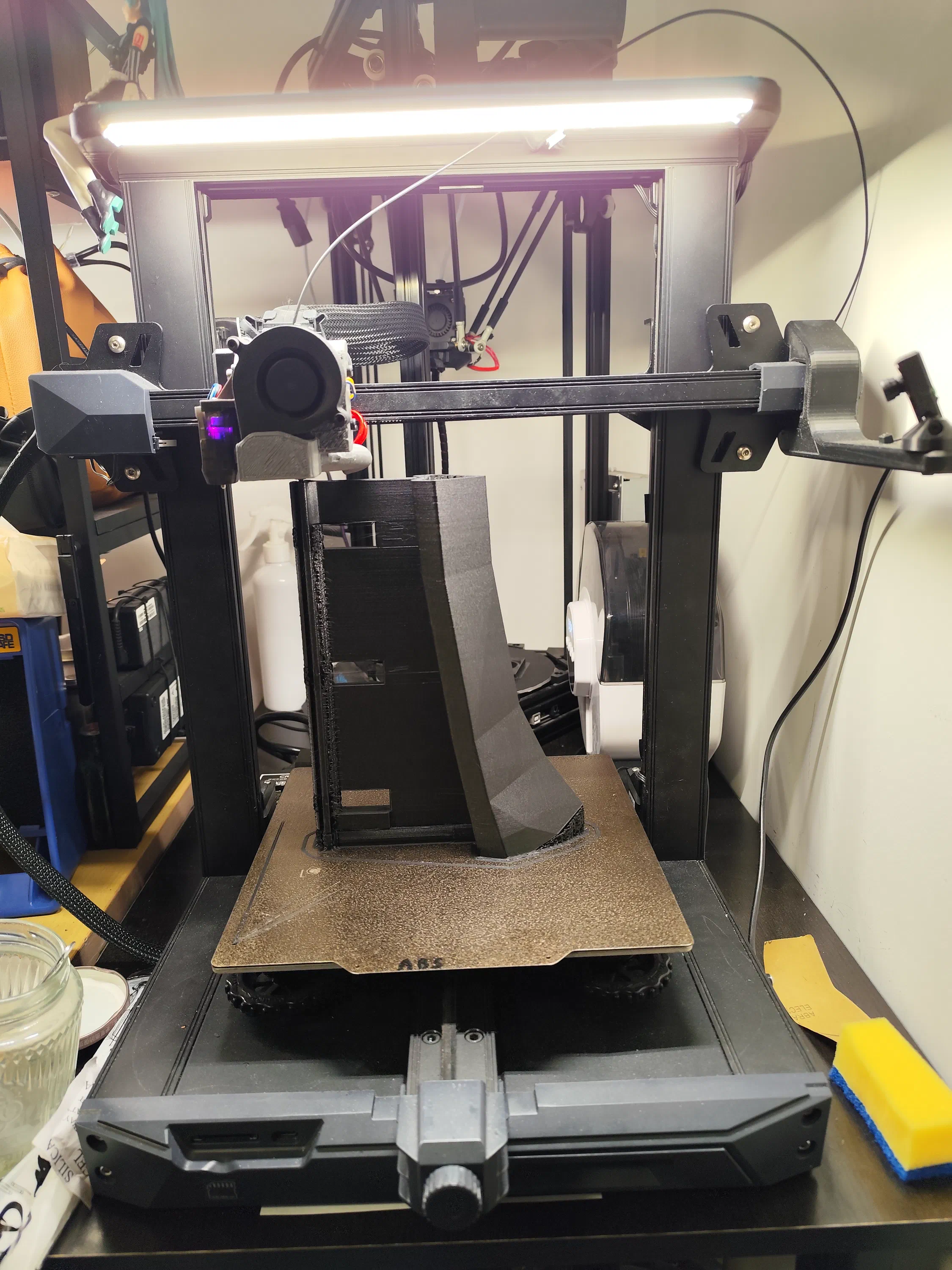
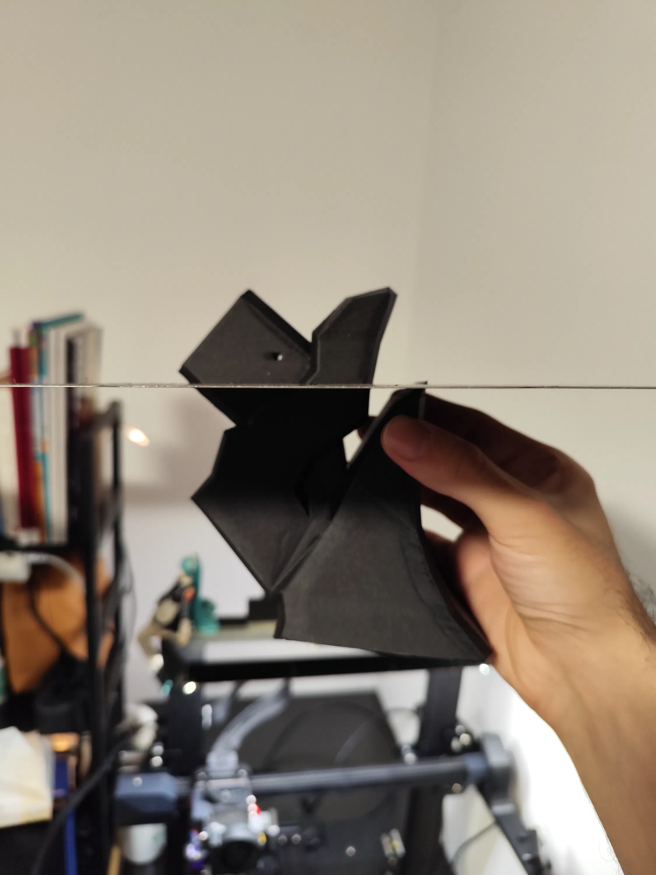
This heavy print schedule also exposed one system bottleneck: with webcam monitoring enabled, the Raspberry Pi Zero2 W occasionally ran out of headroom, causing Klipper timing overflows and mid-print stops.
Luckily, logs made it possible to recover from specific layers and salvage affected prints by resuming and bonding sections where necessary.
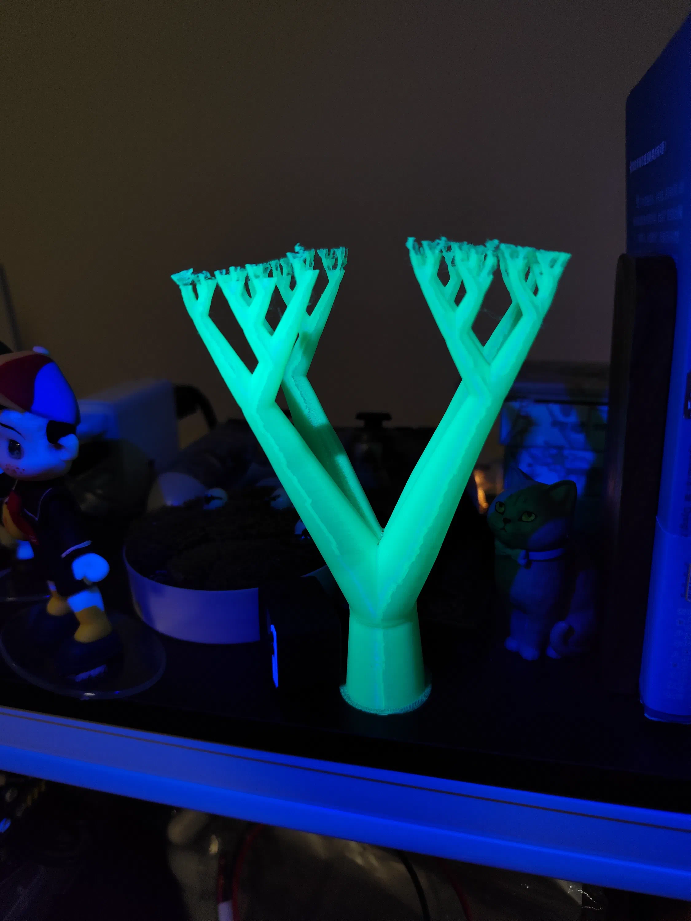
Next came the fluorescent core pieces. Under UV illumination, they looked excellent while printing:
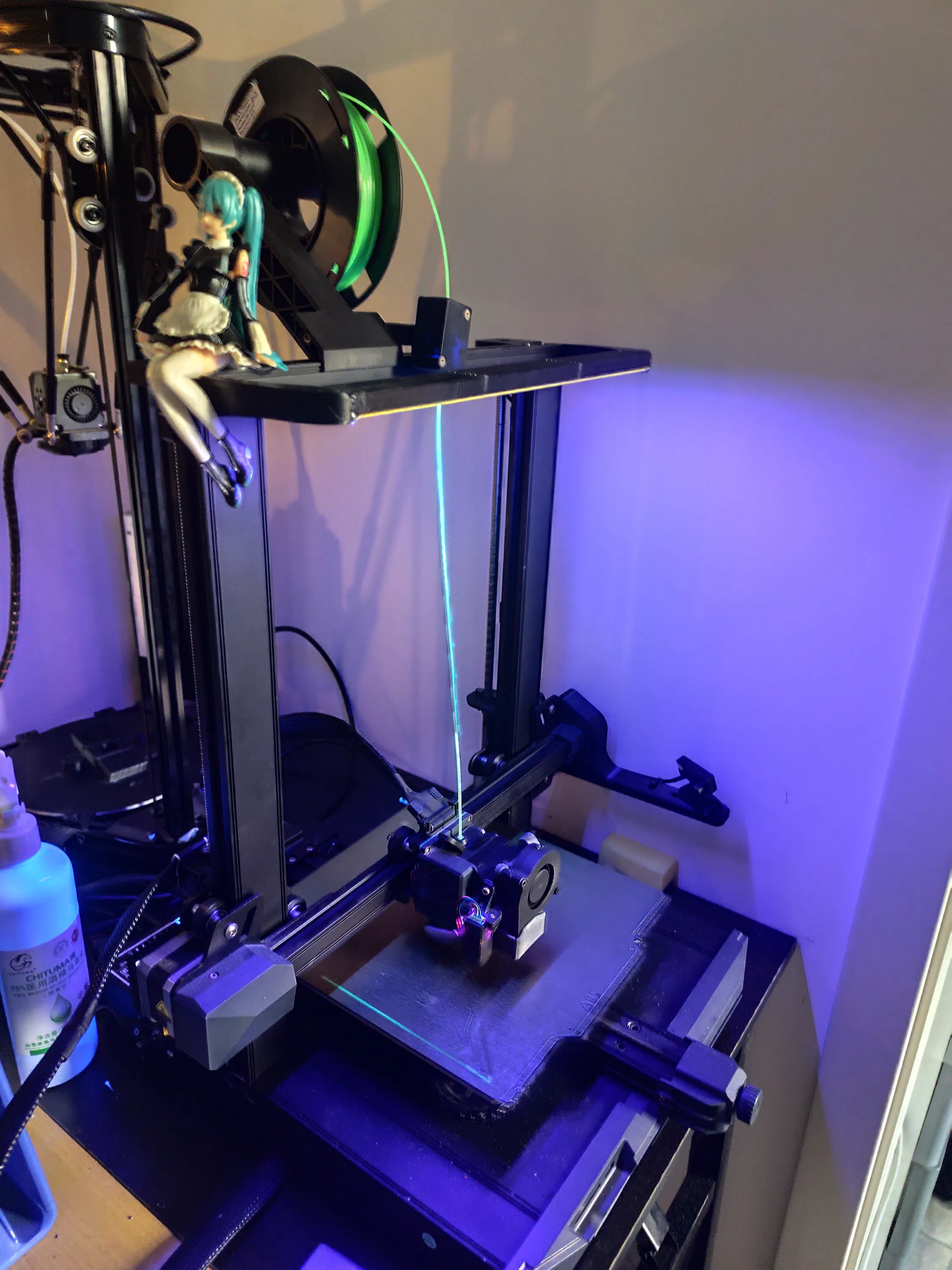
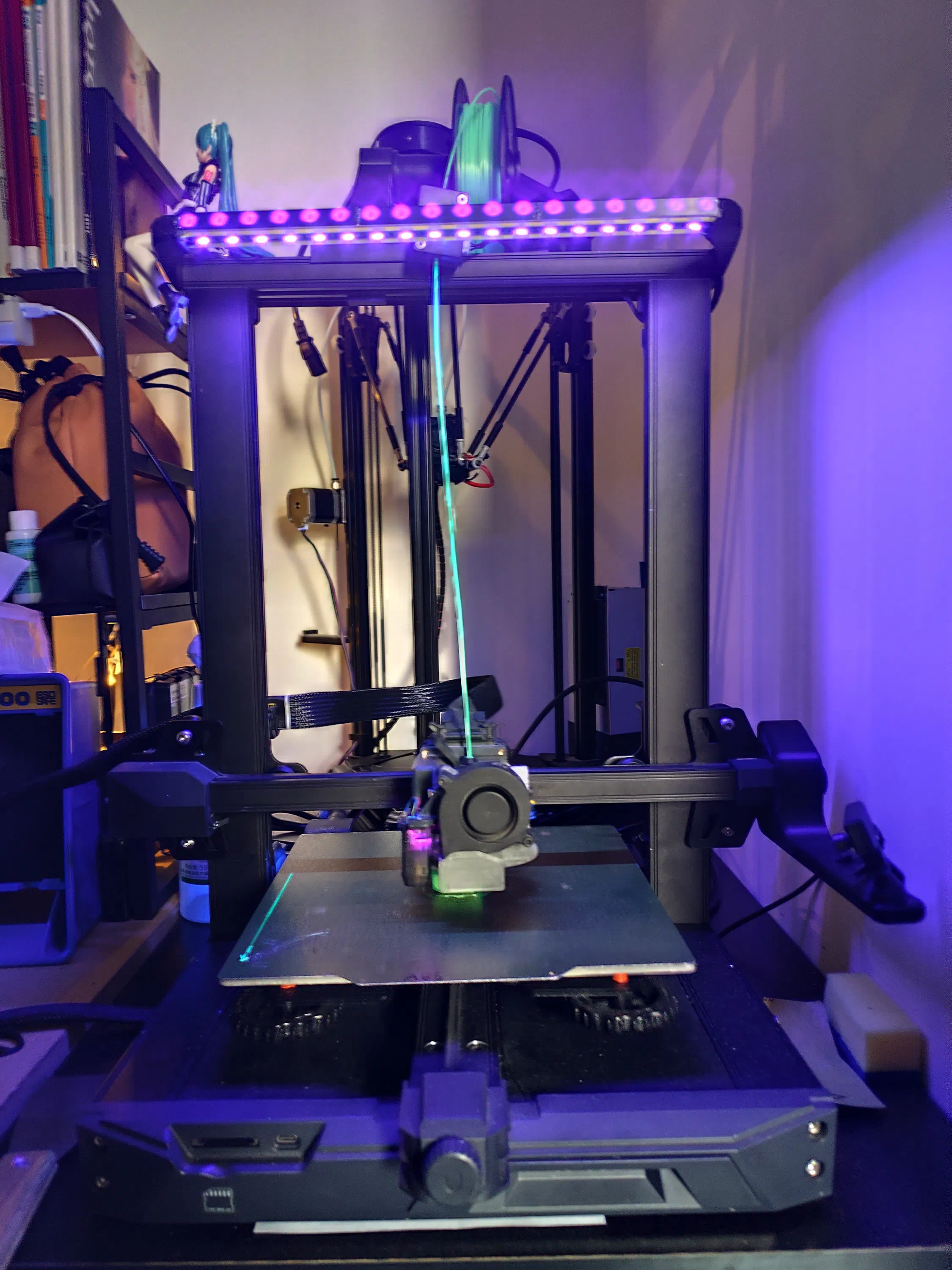
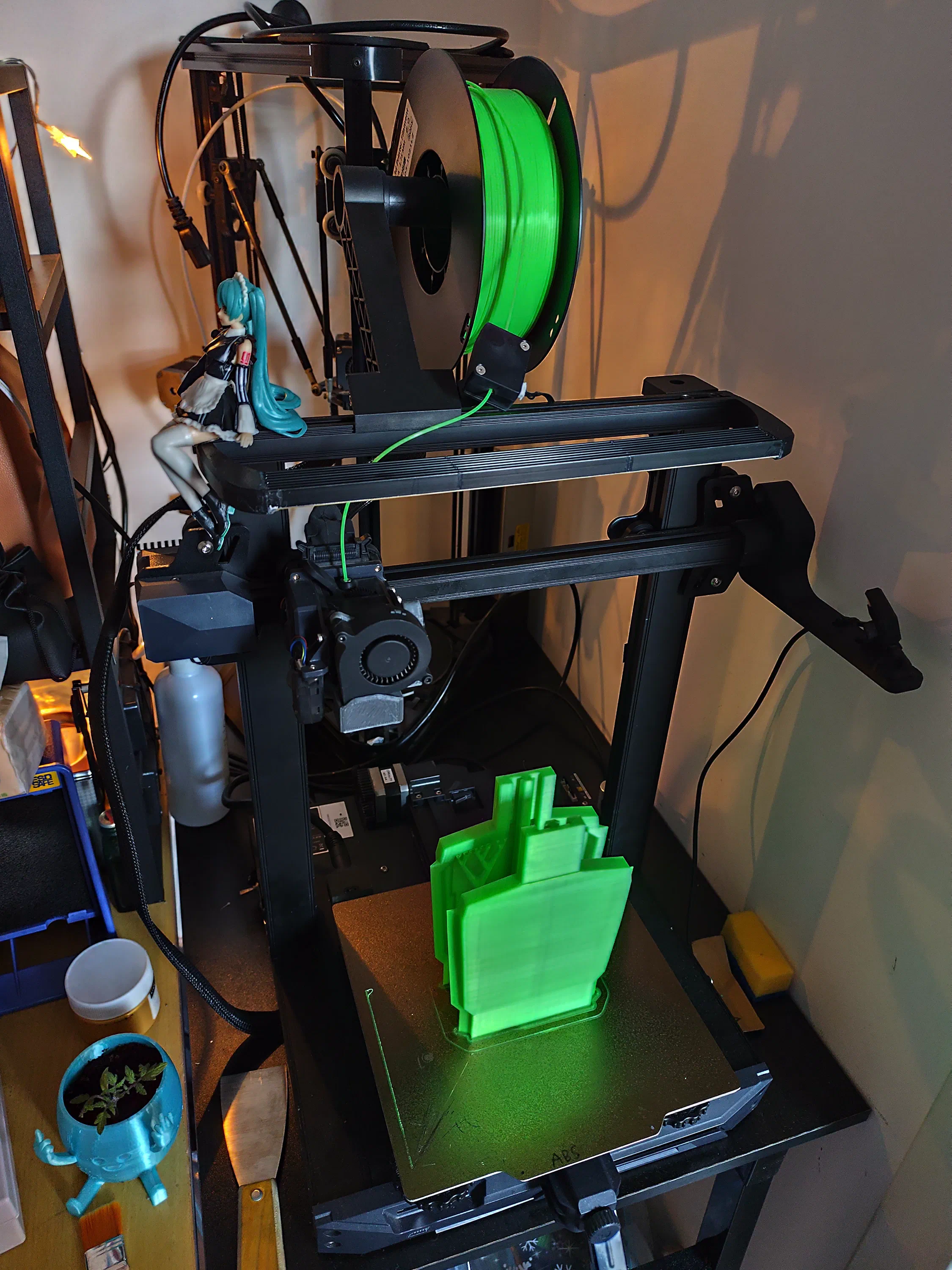
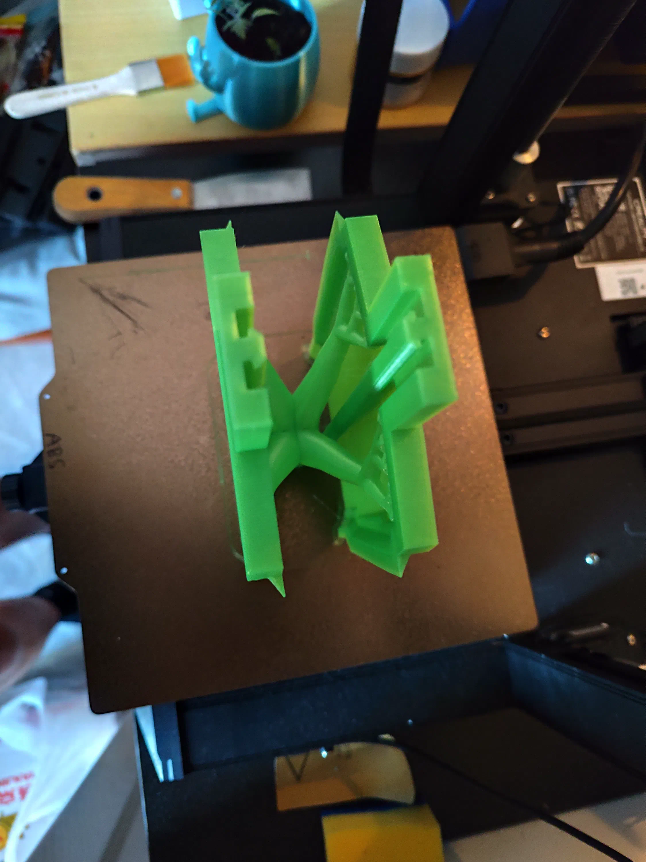
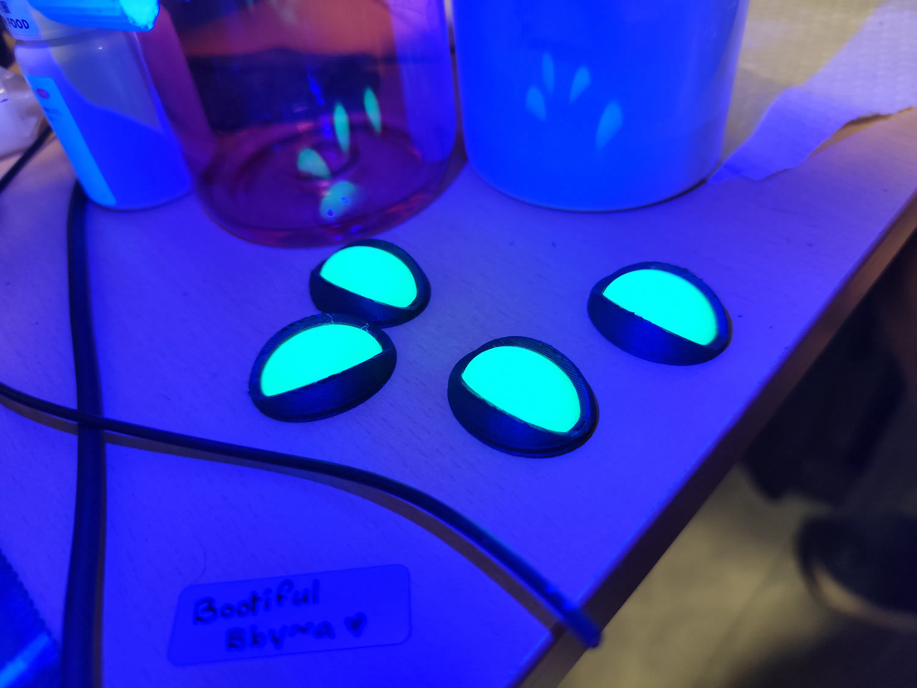
Tree supports were especially useful for these thin upright parts, reducing waste of the relatively expensive fluorescent filament compared with denser conventional supports.
Assembly
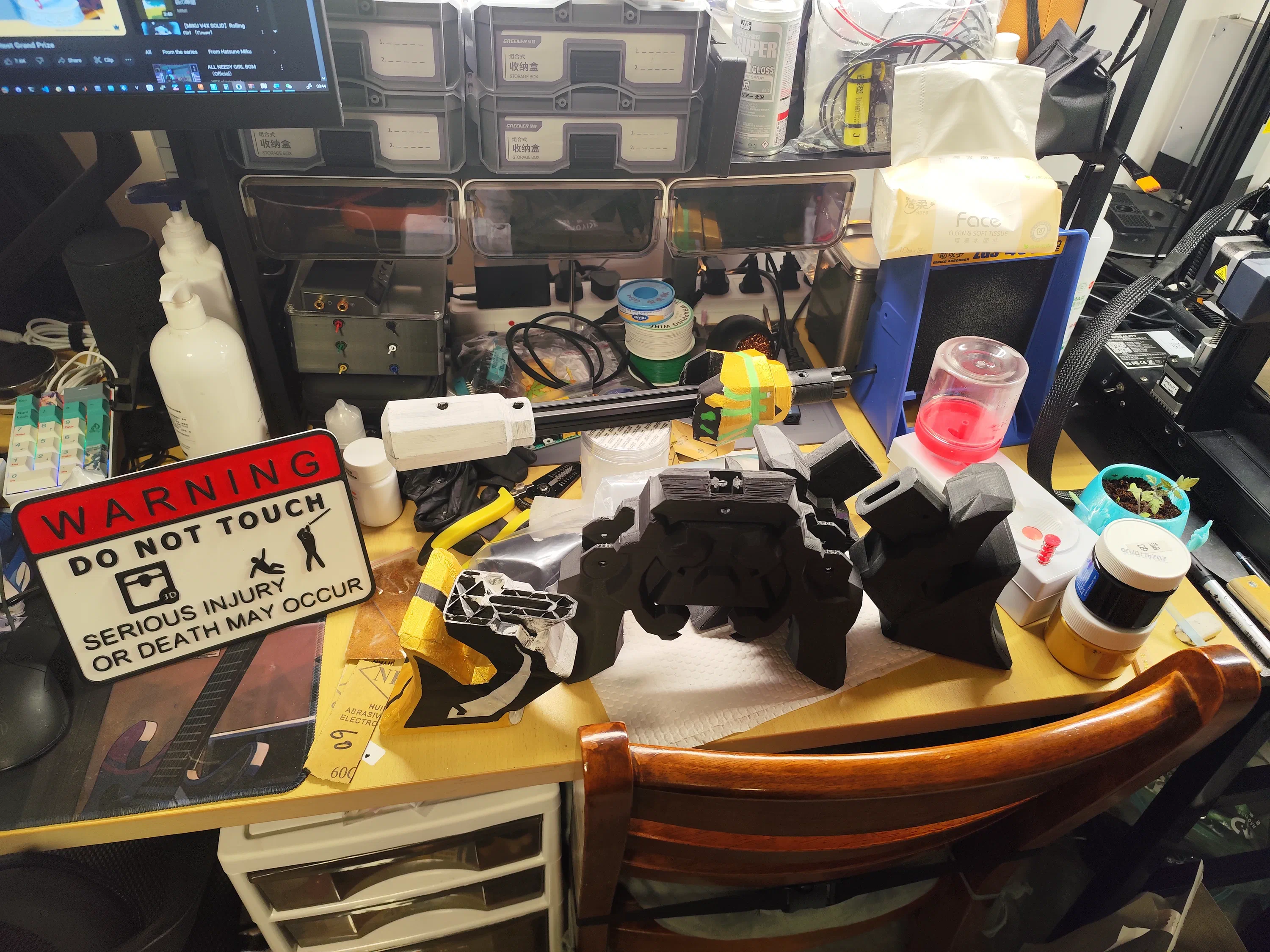
After all parts were printed, final mechanical assembly began. Some pieces had already been prepped or painted, but the structural and electrical integration came first.
Cross-Guard
The first assembly steps involved drilling and slotting the 2020 extrusion so power and signal lines could route from the heel switch up to the cross-guard electronics drawers.
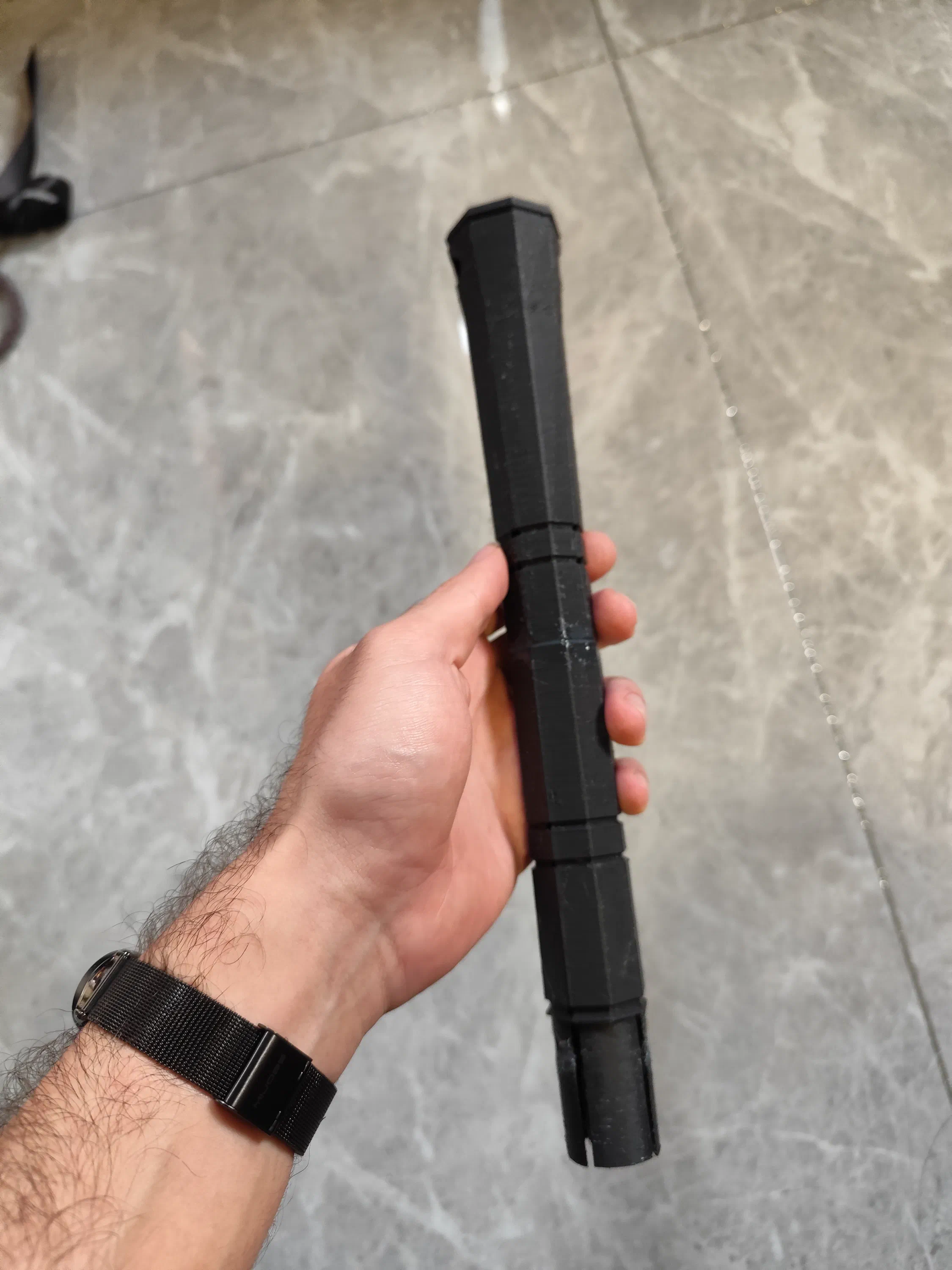
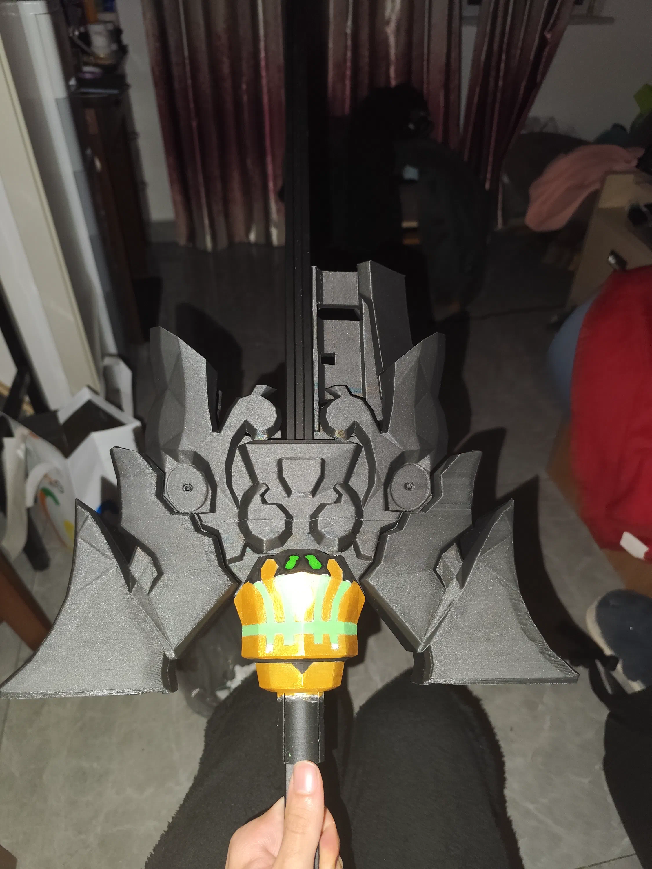
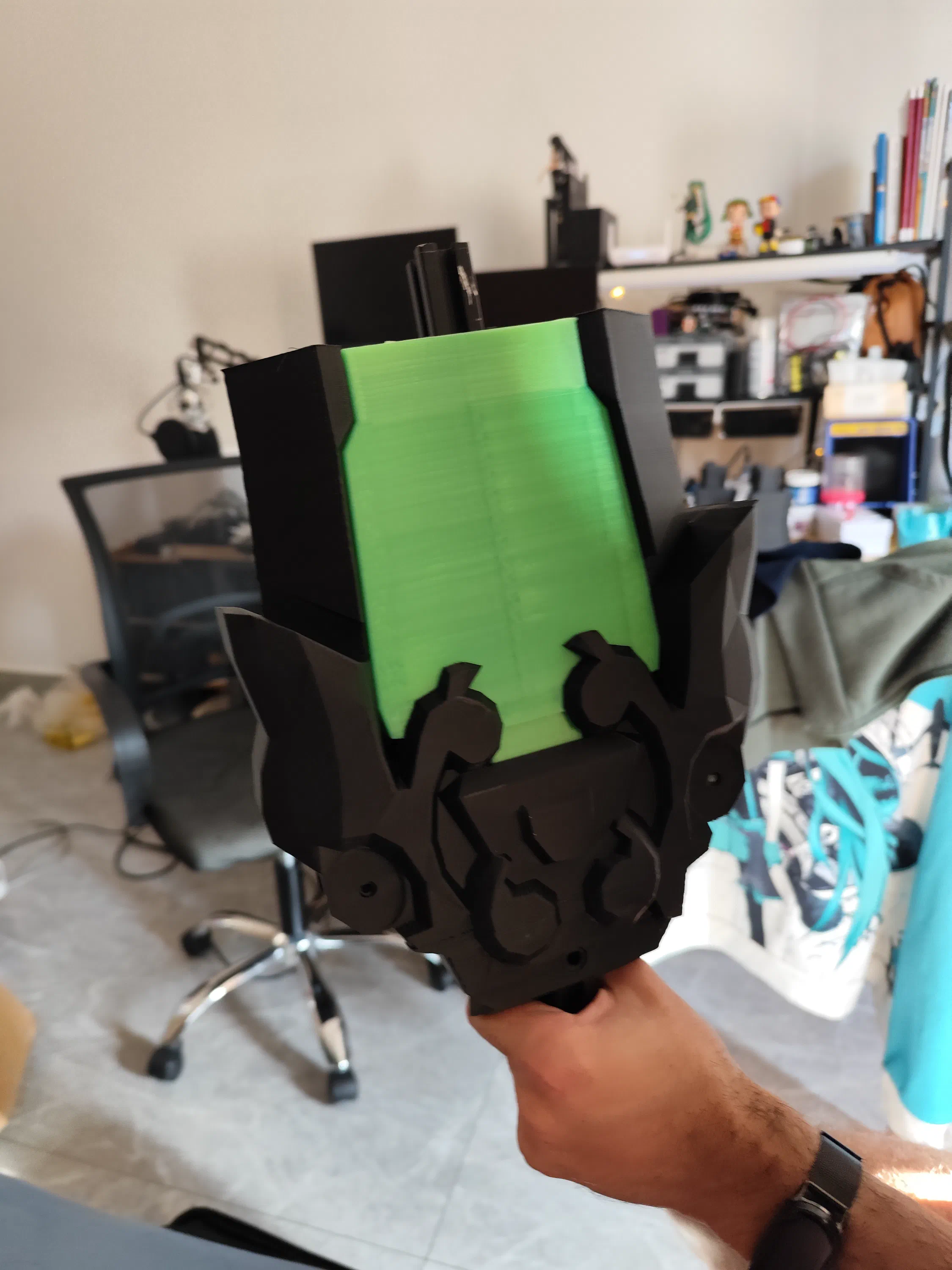
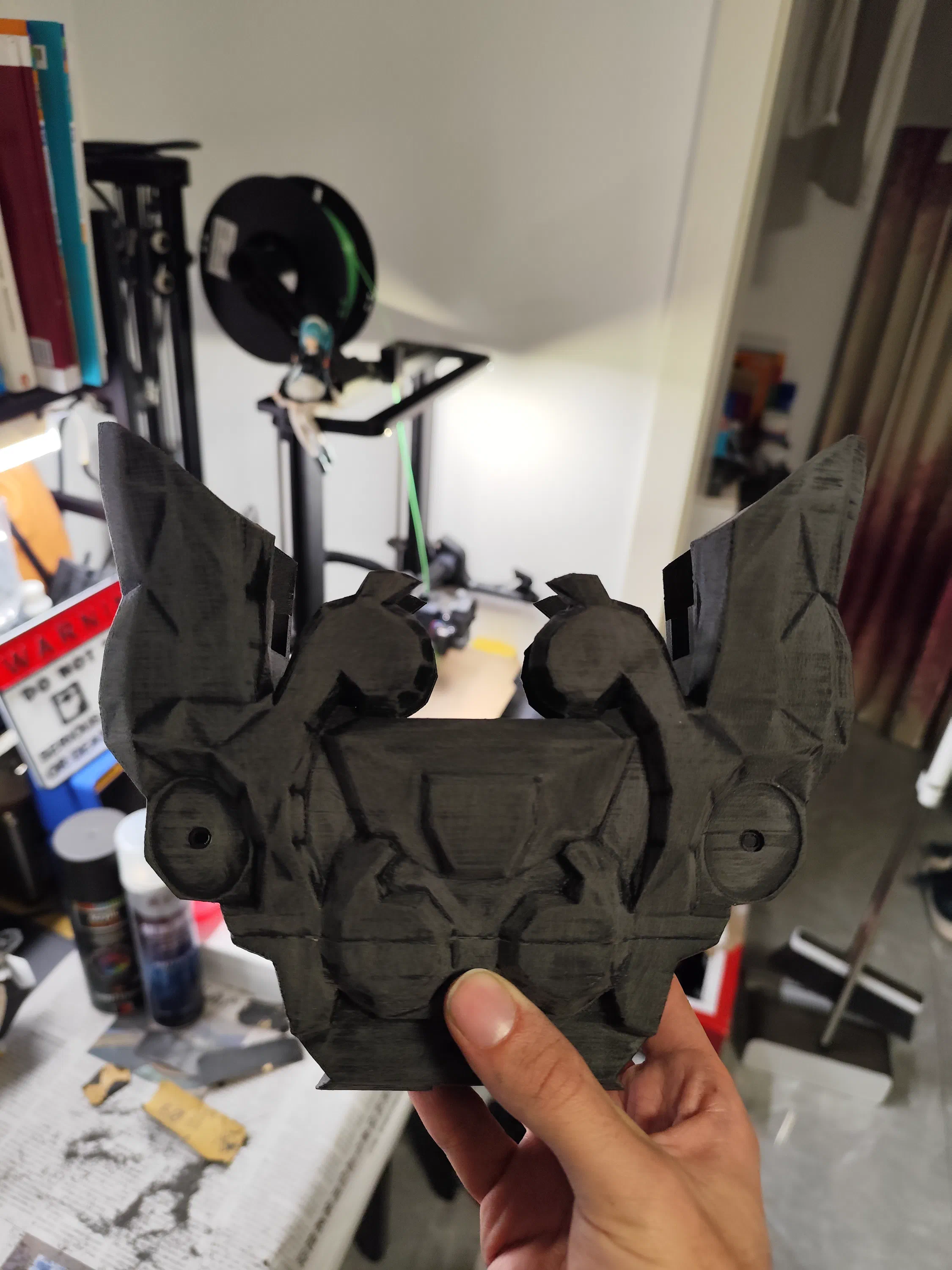
The two handle halves were additionally reinforced with 2mm steel pins, heat-set into the printed parts for stronger coupling.
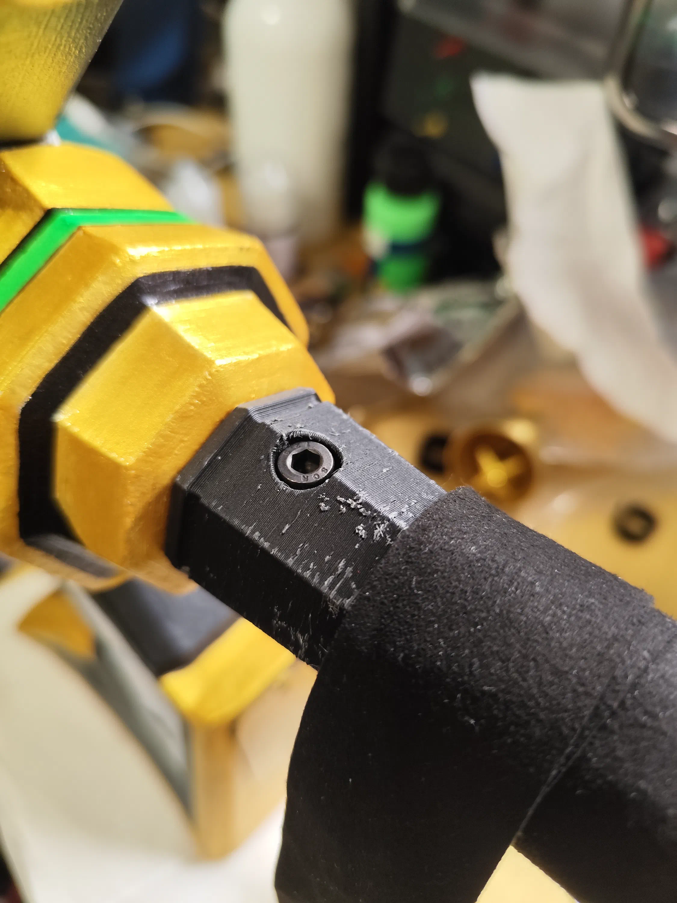
At this stage, the lower sword section finally started to look complete. A lot of attention to seam placement paid off, and the M5 screw/T-nut attachments were hidden with overlapping geometry and the felt handle wrap.
Grooves in the handle were intentionally included to lock the waxed flat-woven string pattern into place.
Blade Edge
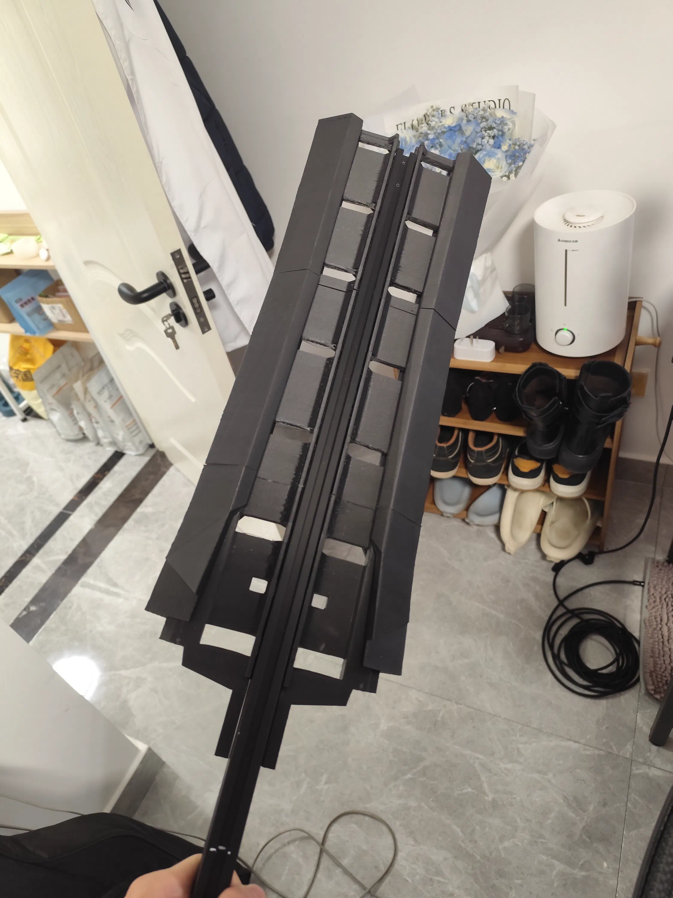
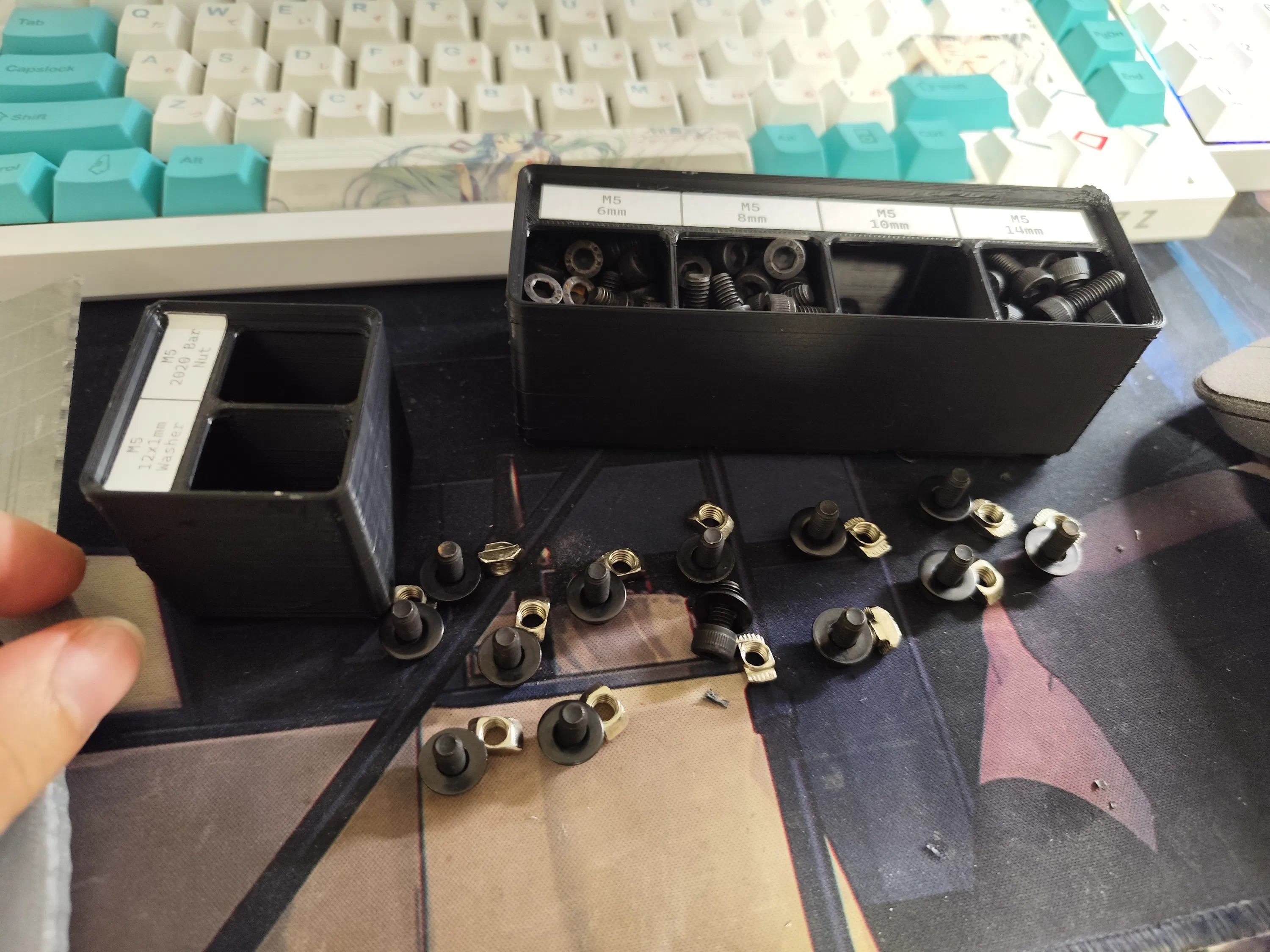
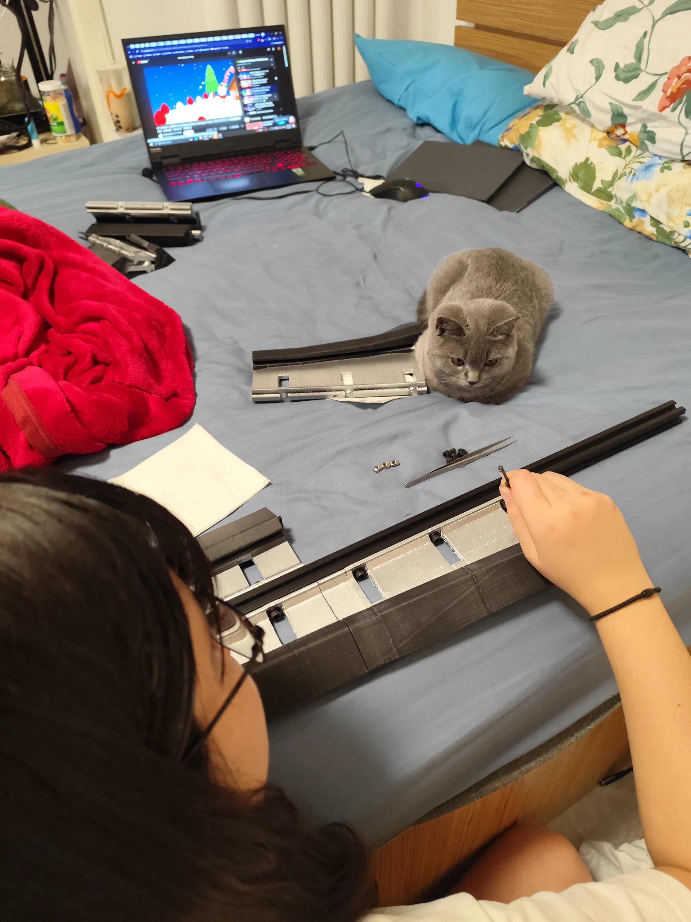
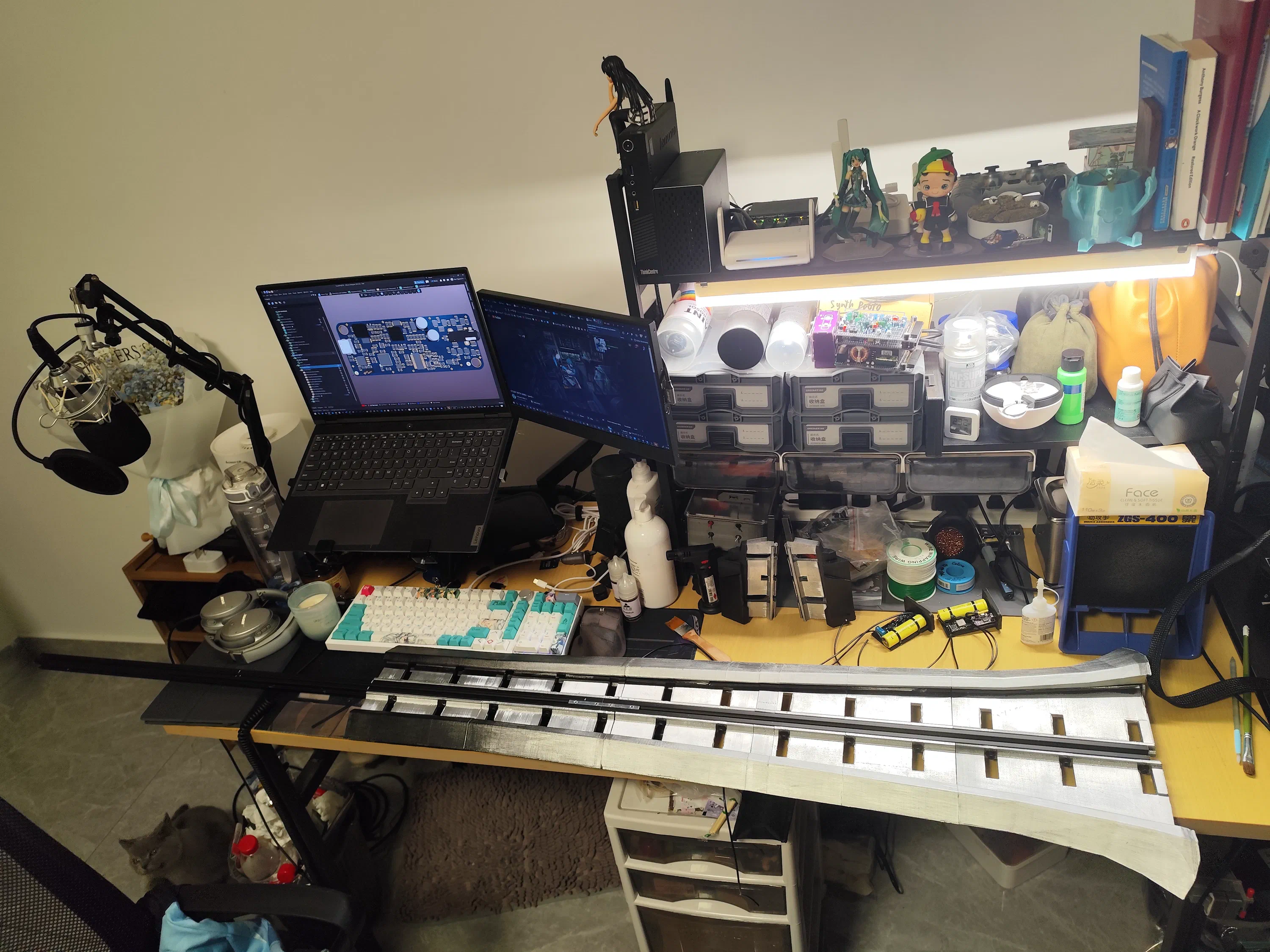
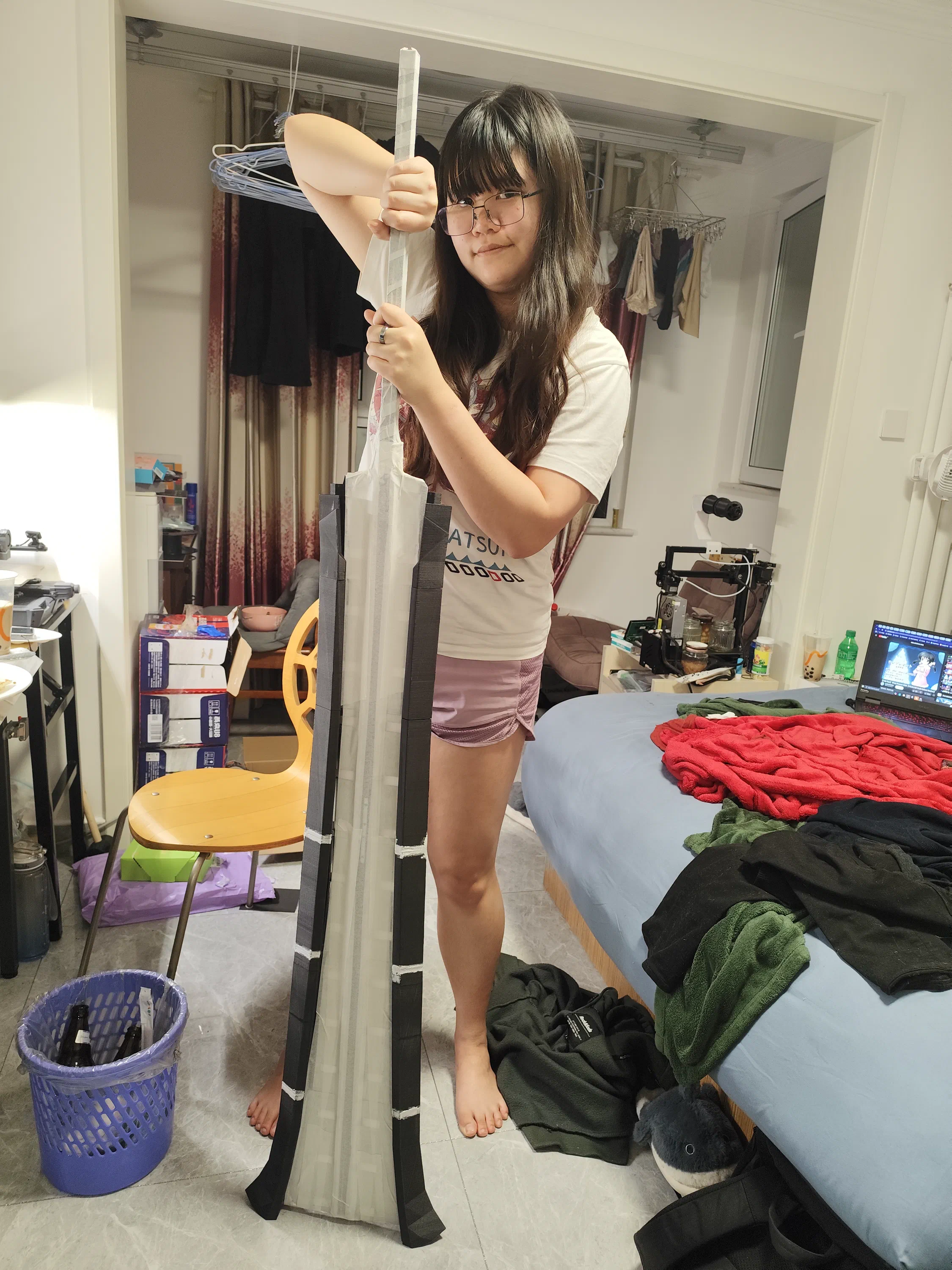
Next, blade edge modules were slid on and fixed using additional M5 screws and T-nuts, 26 fasteners total across both sides for stiffness and impact resistance.
UV LED Strips
With edge structures in place, UV LED strips were mounted along top and bottom channels on each side, with extra segments added near the wider blade tip.
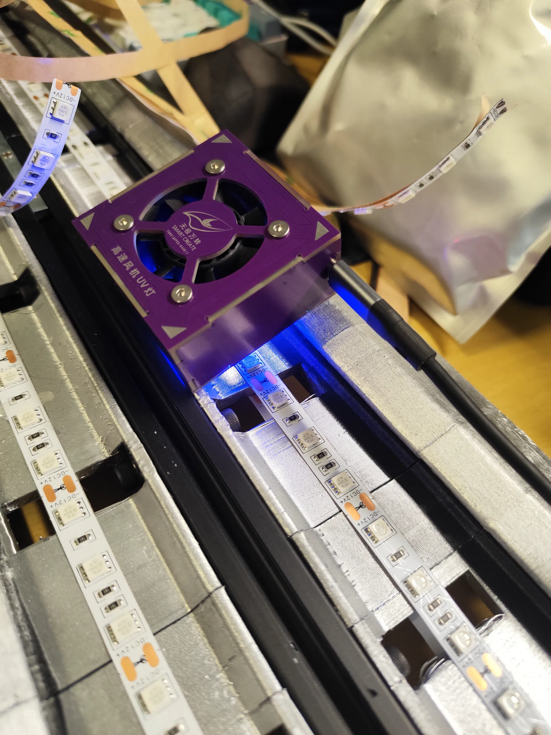
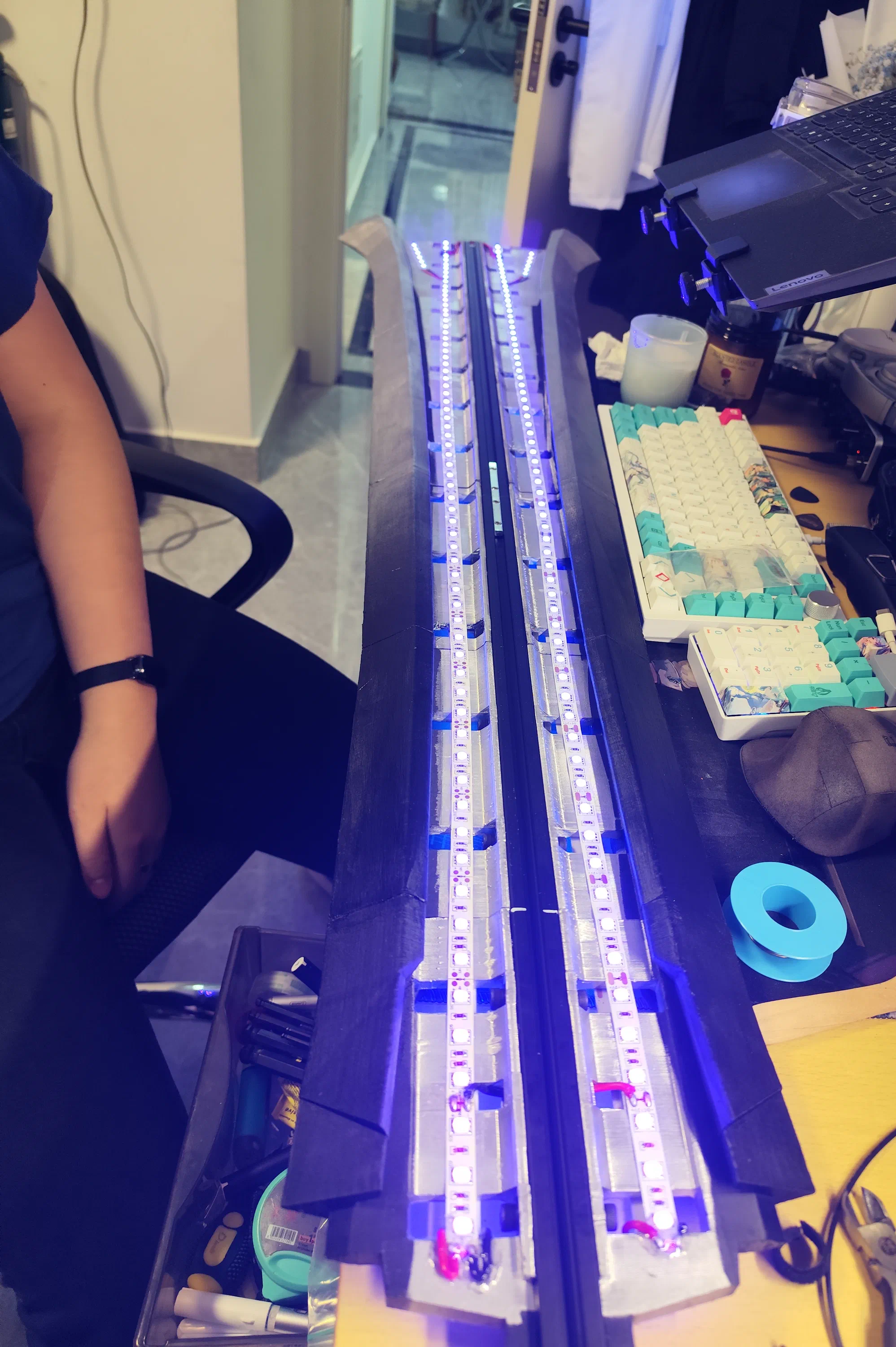
Since stock strip adhesive is unreliable over time, I added UV-resin cross-over anchors to secure the strips mechanically. Then came a full-power illumination test.
Glow Core Panels
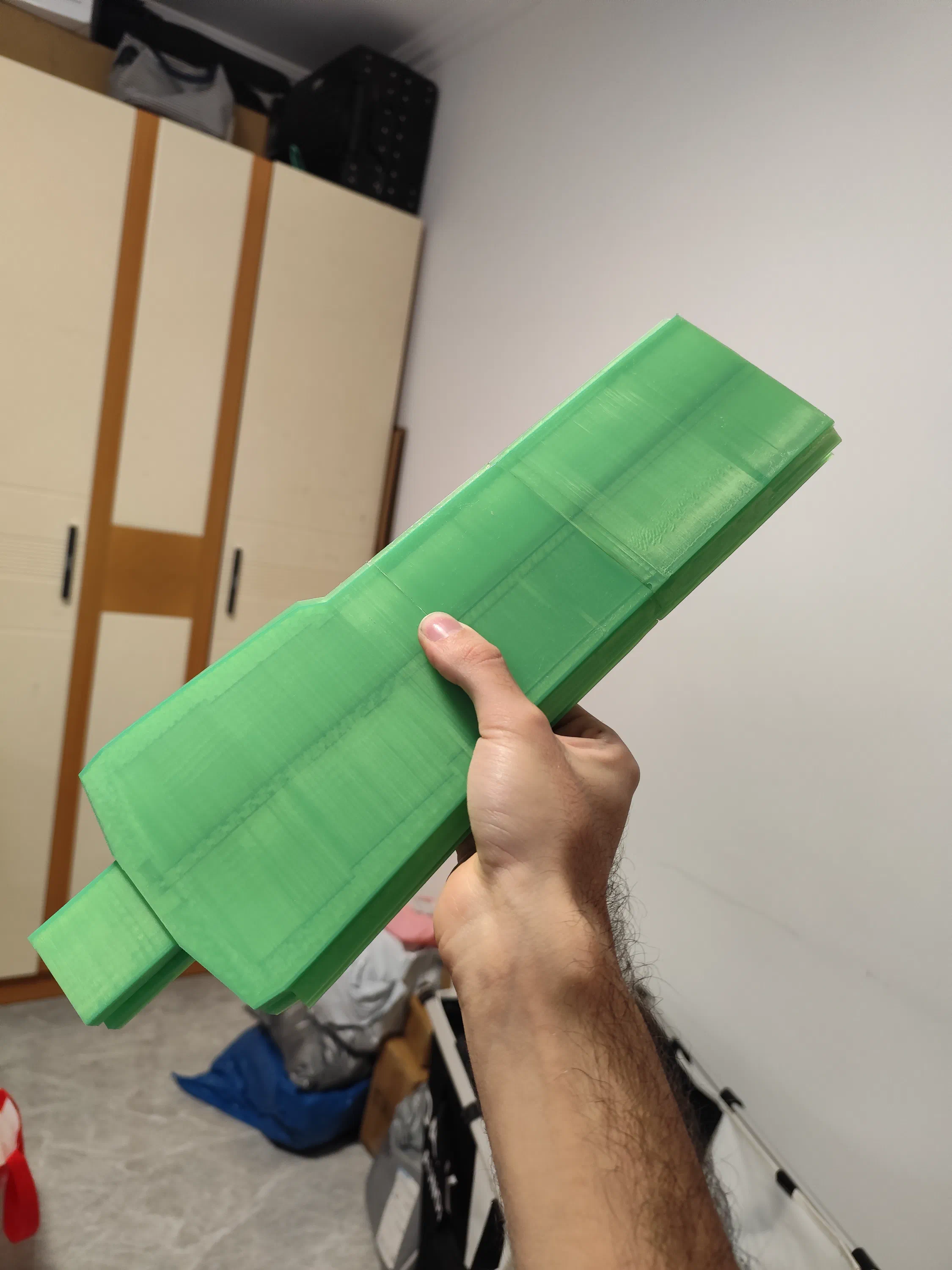
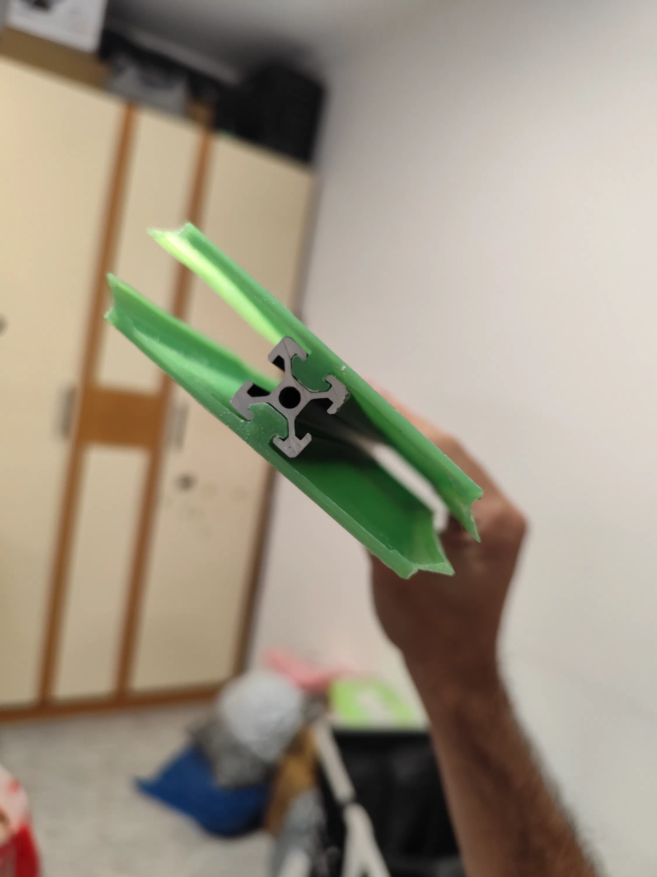
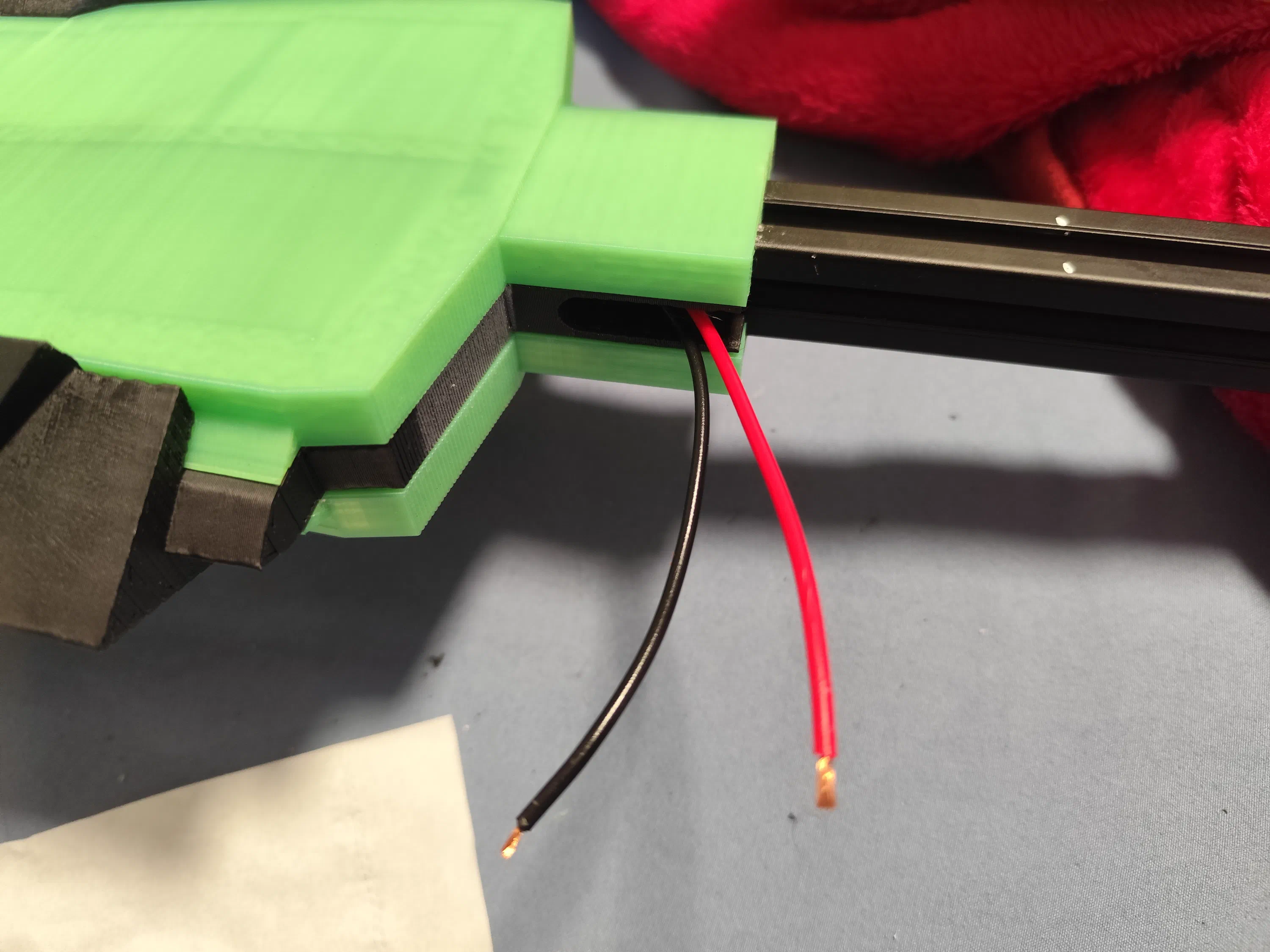
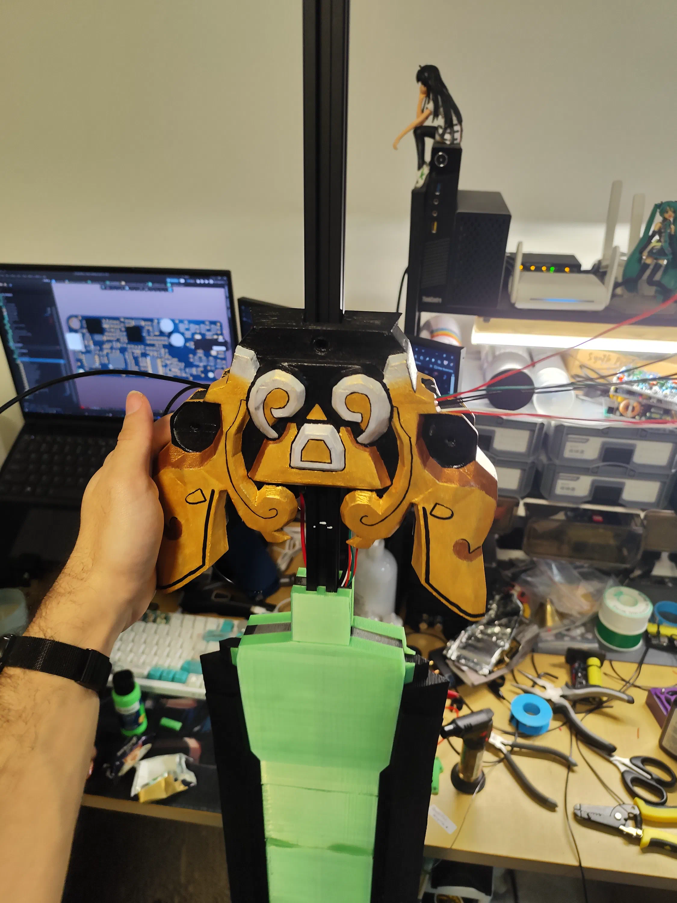
The glow core panels were then slid into place while carefully threading heavier-gauge supply wires feeding the strip network.
Electronics Drawers
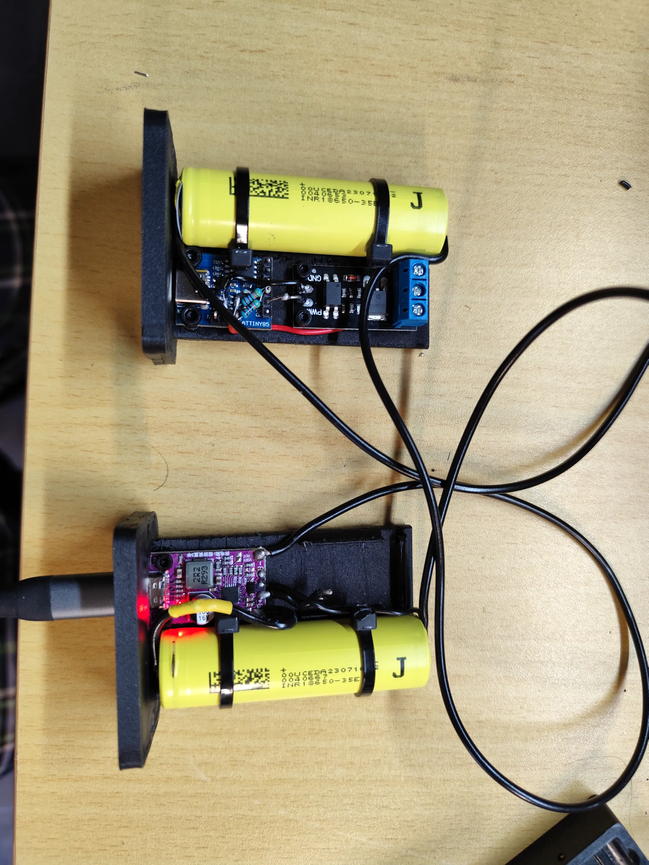
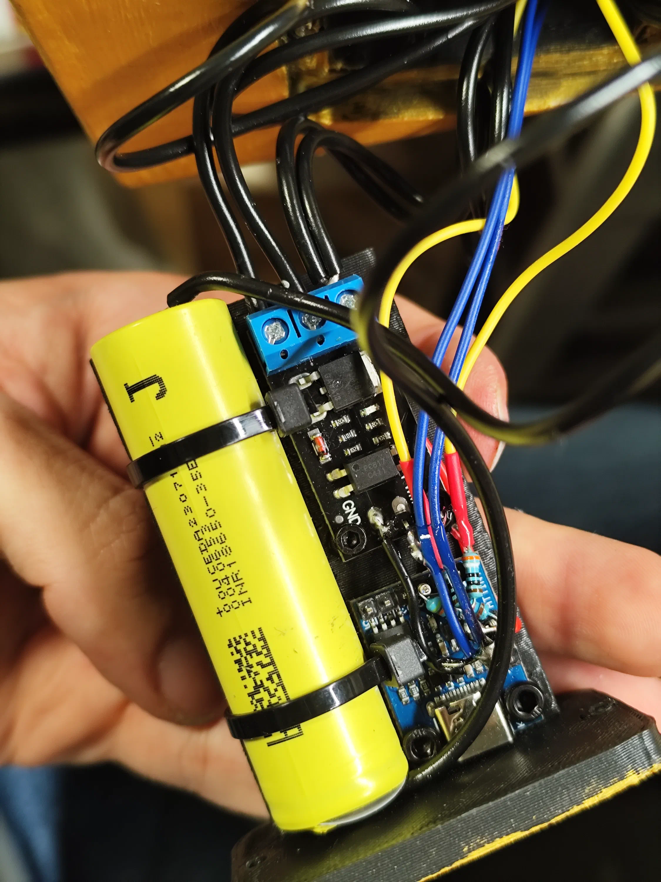
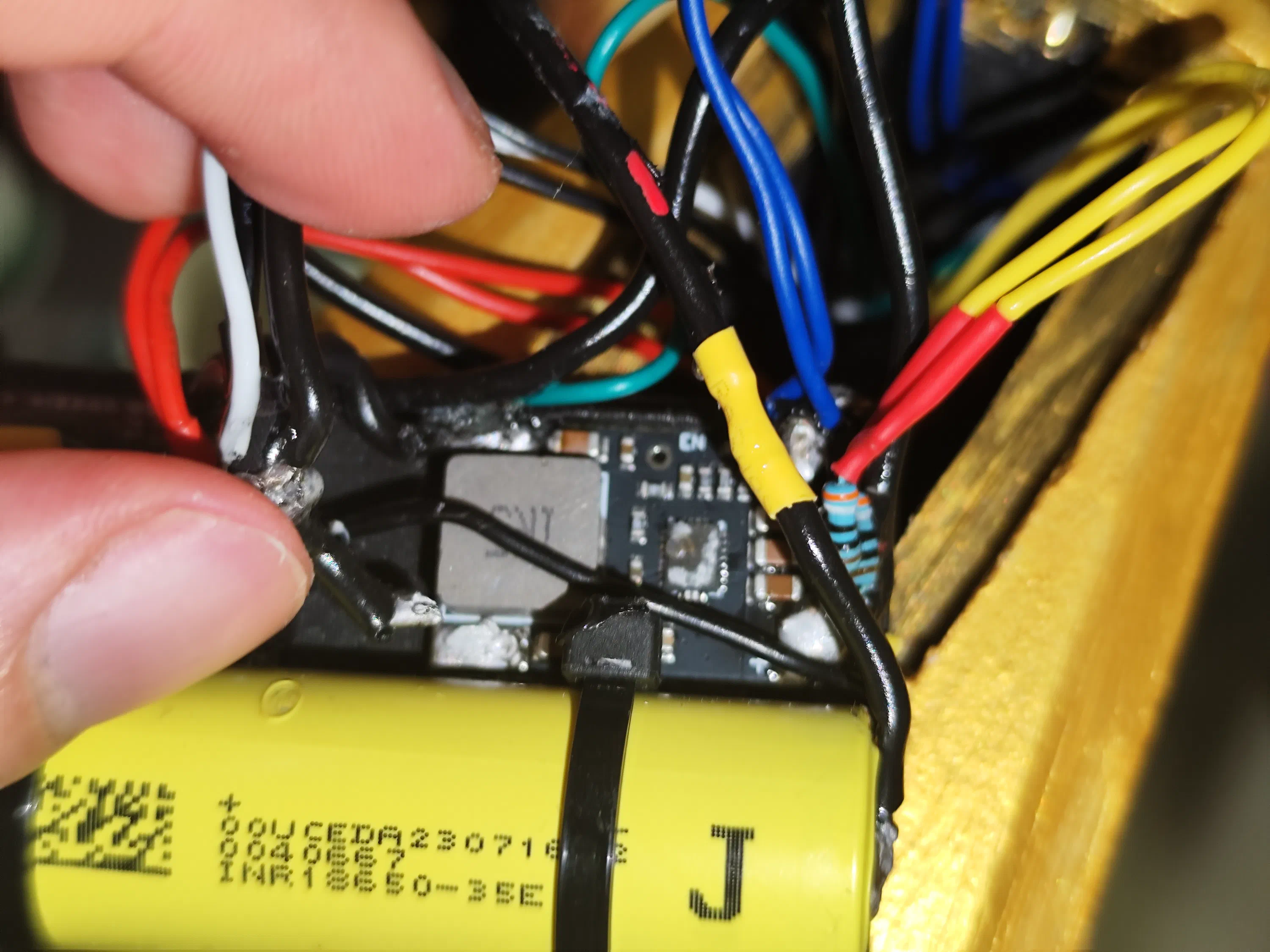
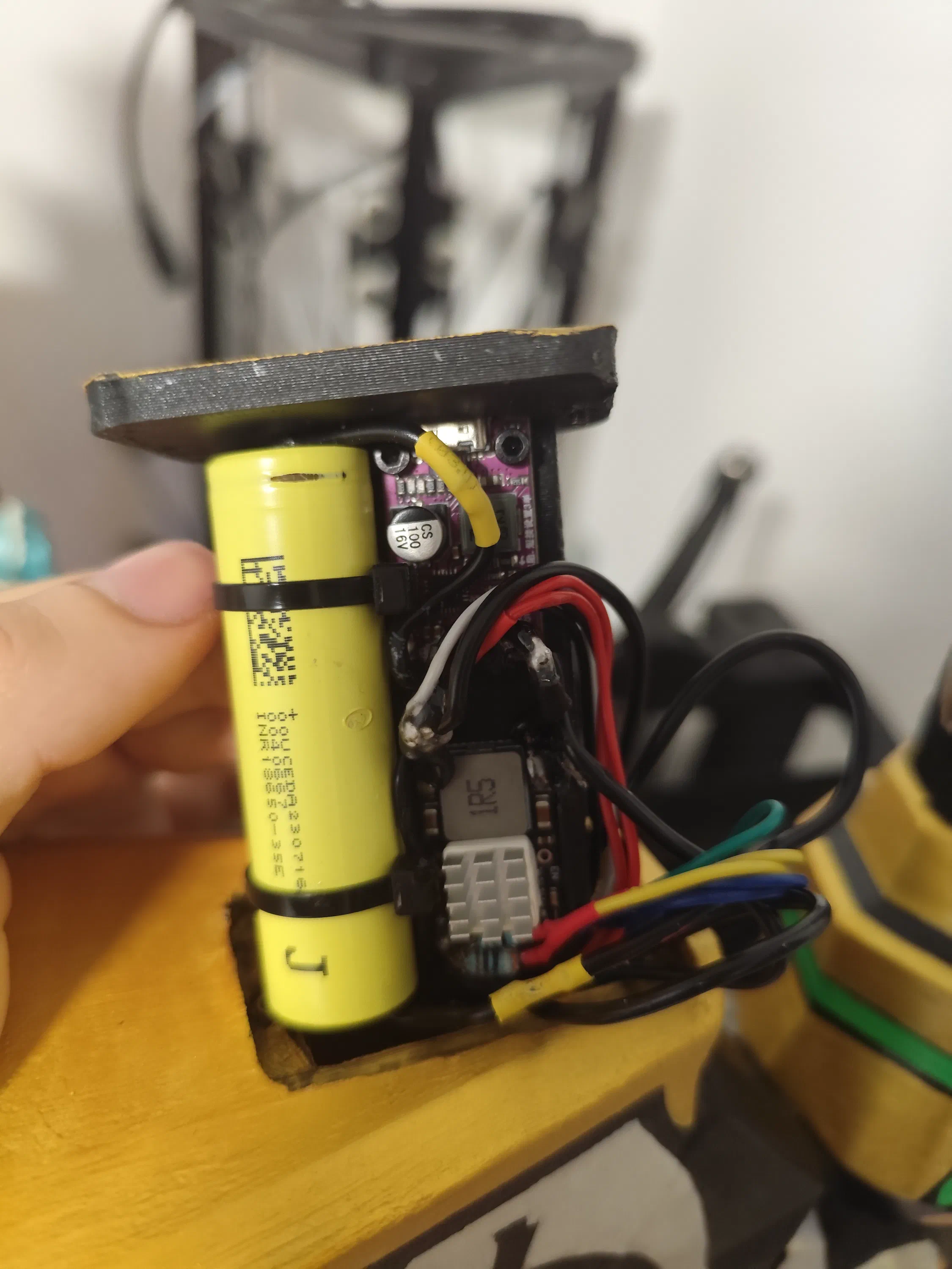
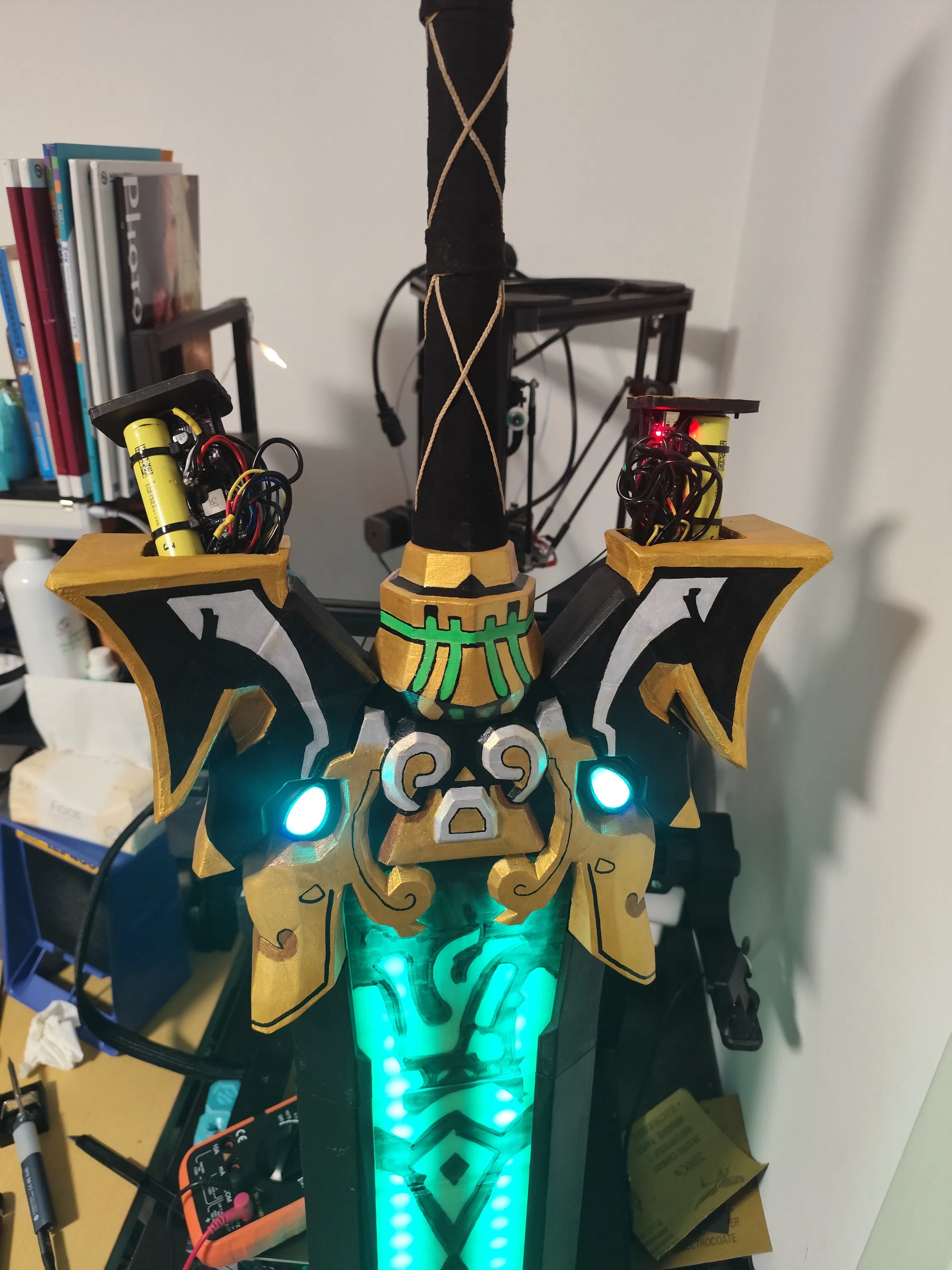
Finally, both electronics drawers were fully assembled, inserted into the cross-guard, and secured with M3 screws and inserts:
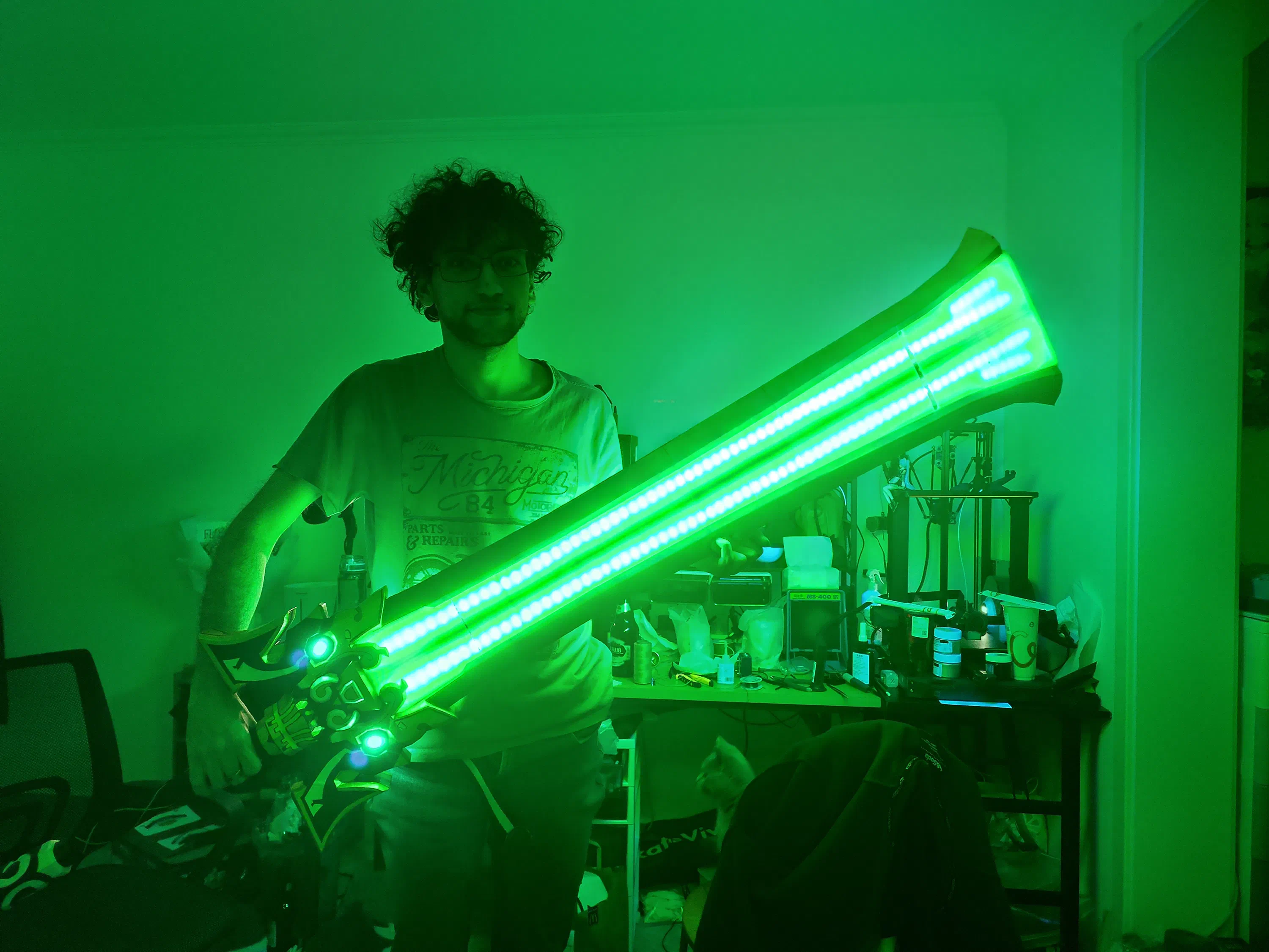
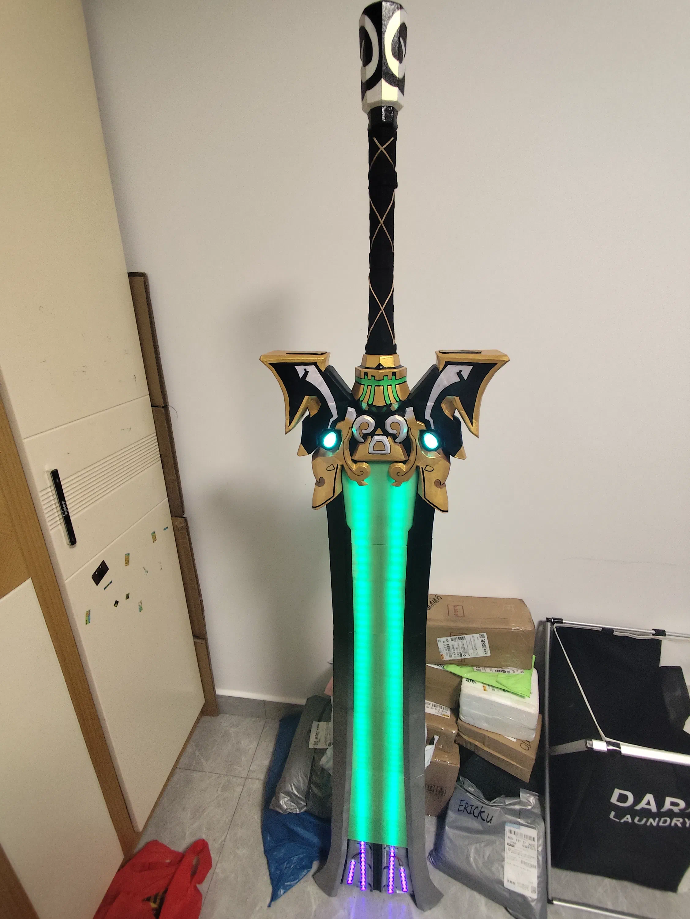
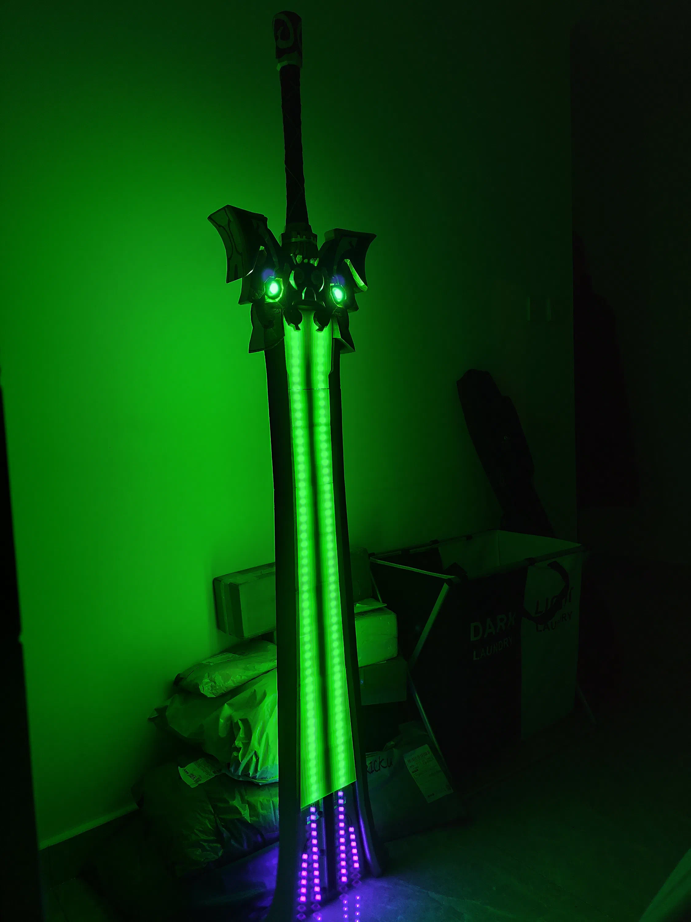
In operation, the 12V boost converters were running close to their ~3A region to supply nearly 3 meters of LED strips, which generated significant heat. One converter set failed before final closure, so I added a small heatsink to the converter IC as a reliability fix.
Painting
For the high-detail regions, painting became a major sub-project. Surface preparation followed a full sequence: progressive sanding (200 grit to 800 grit), then a primer layer (gesso + PVA blend), then pencil layout of key lines, and finally hand-painted acrylic details.
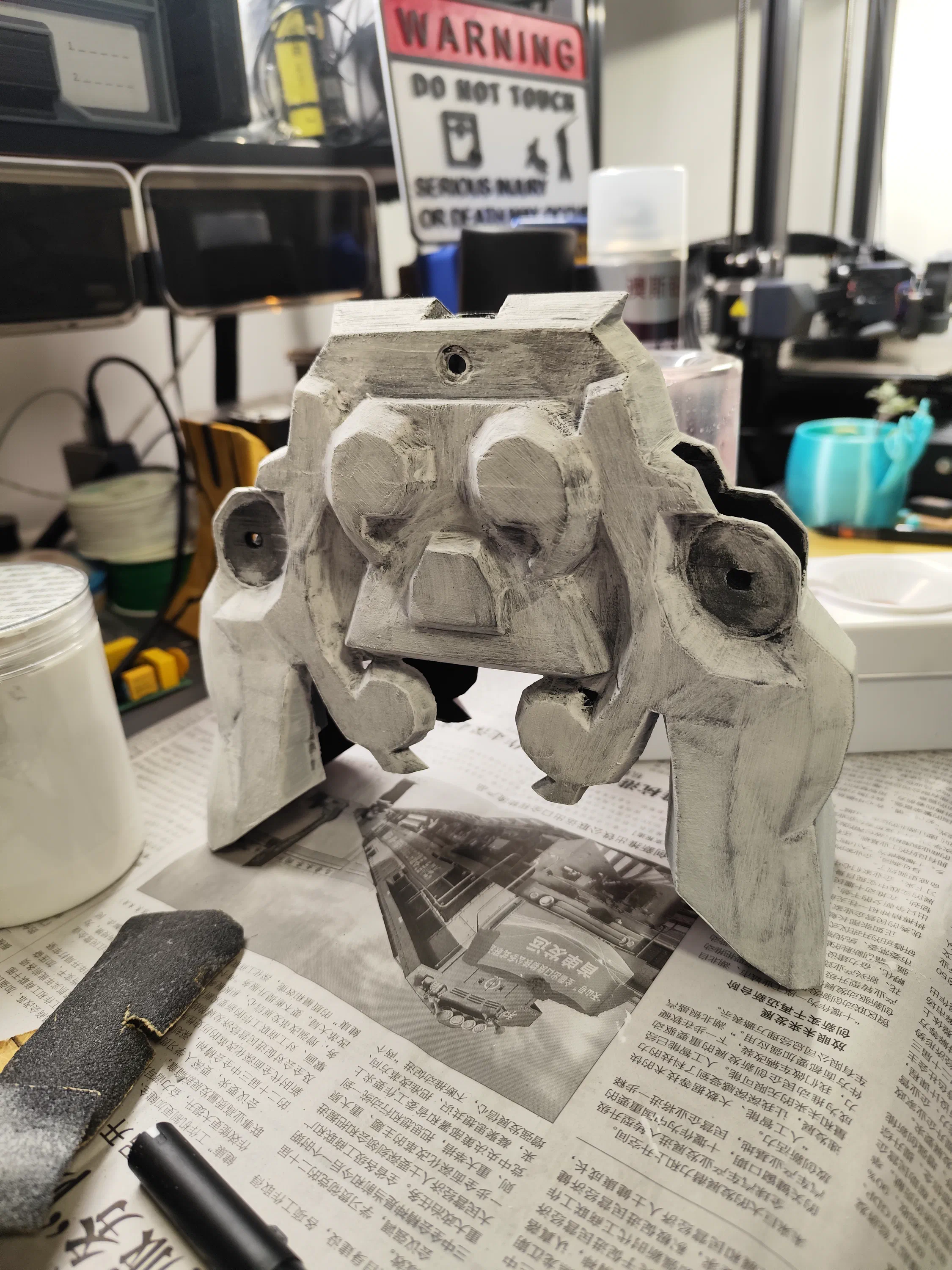
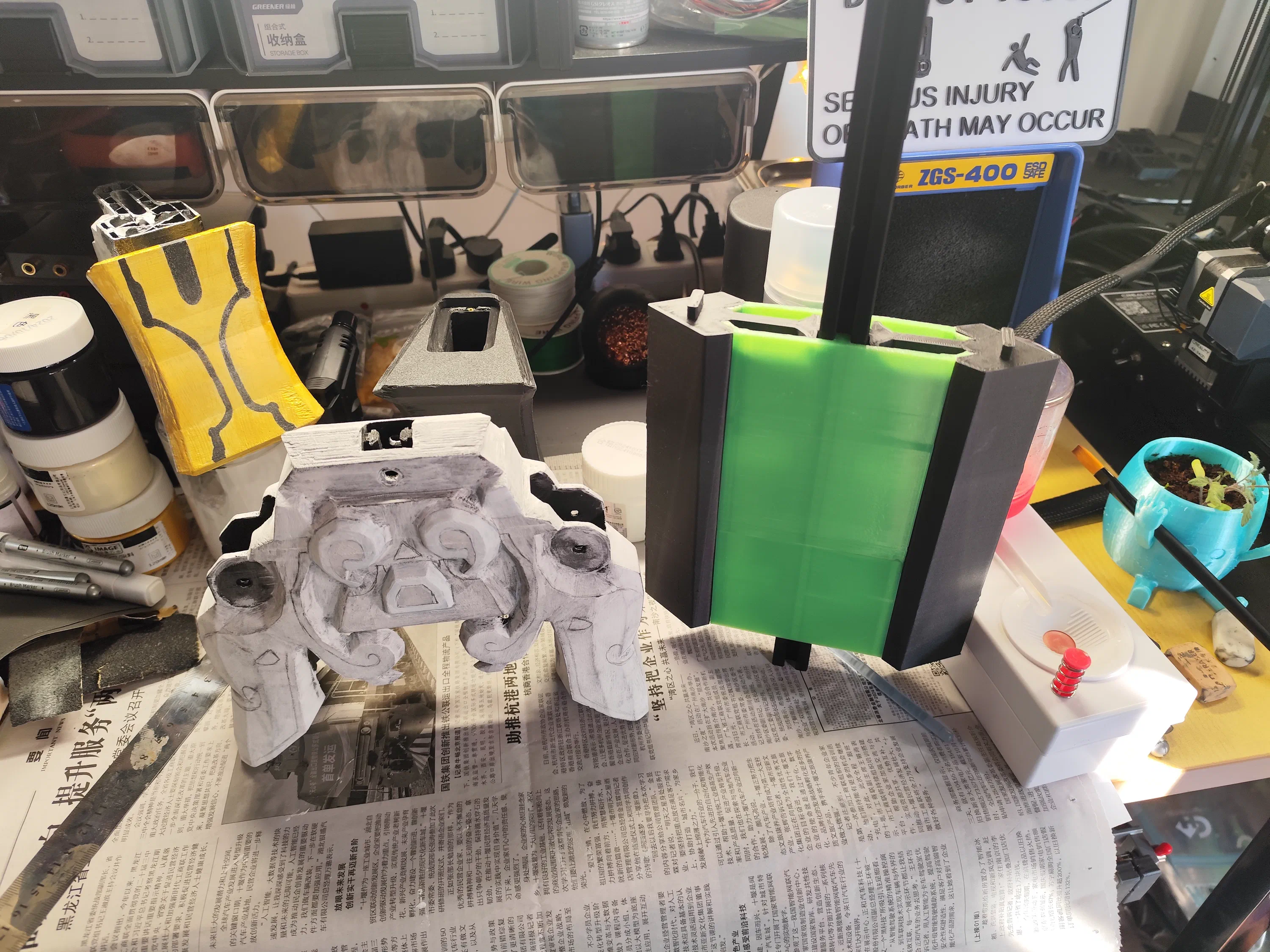
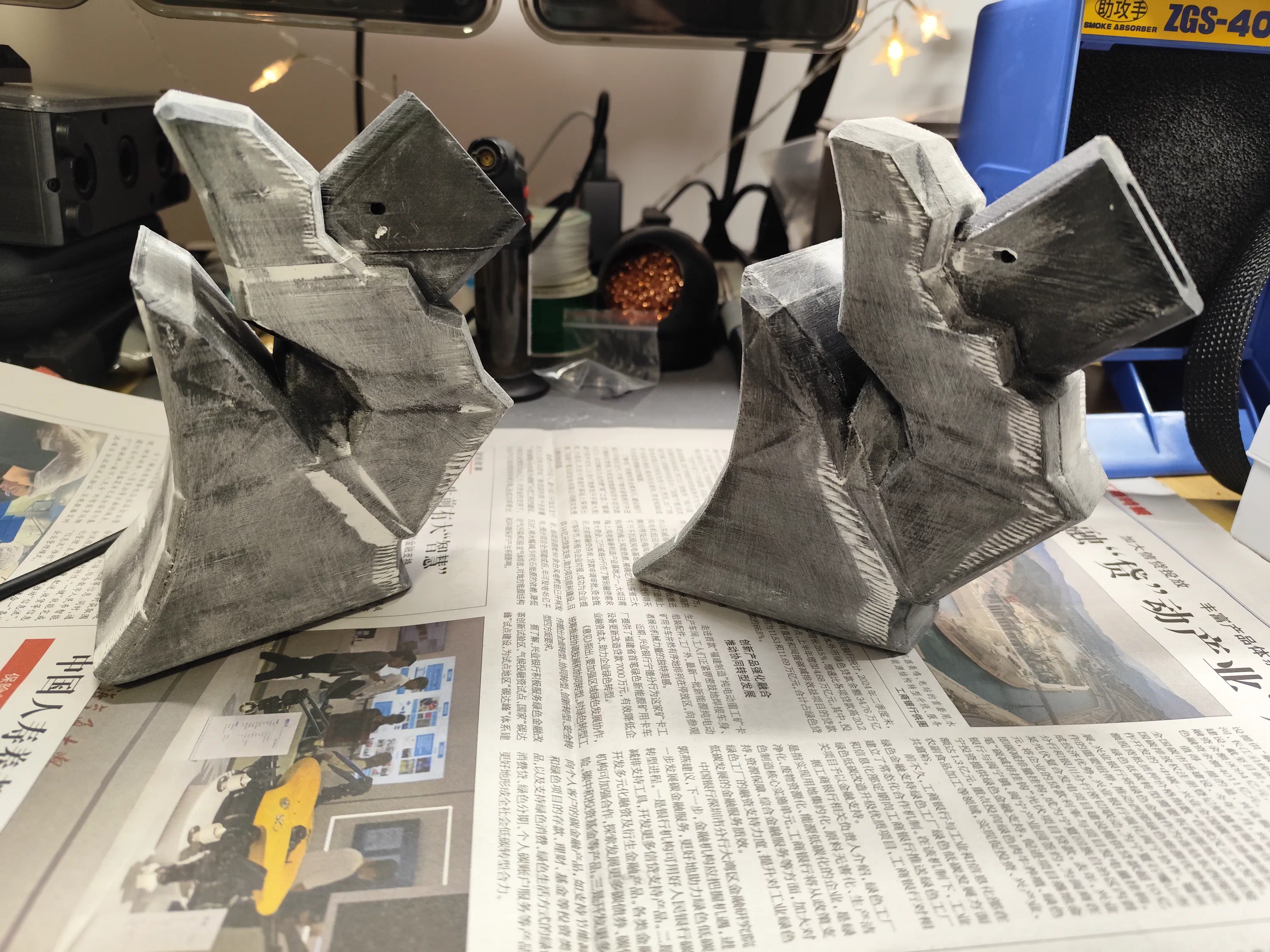
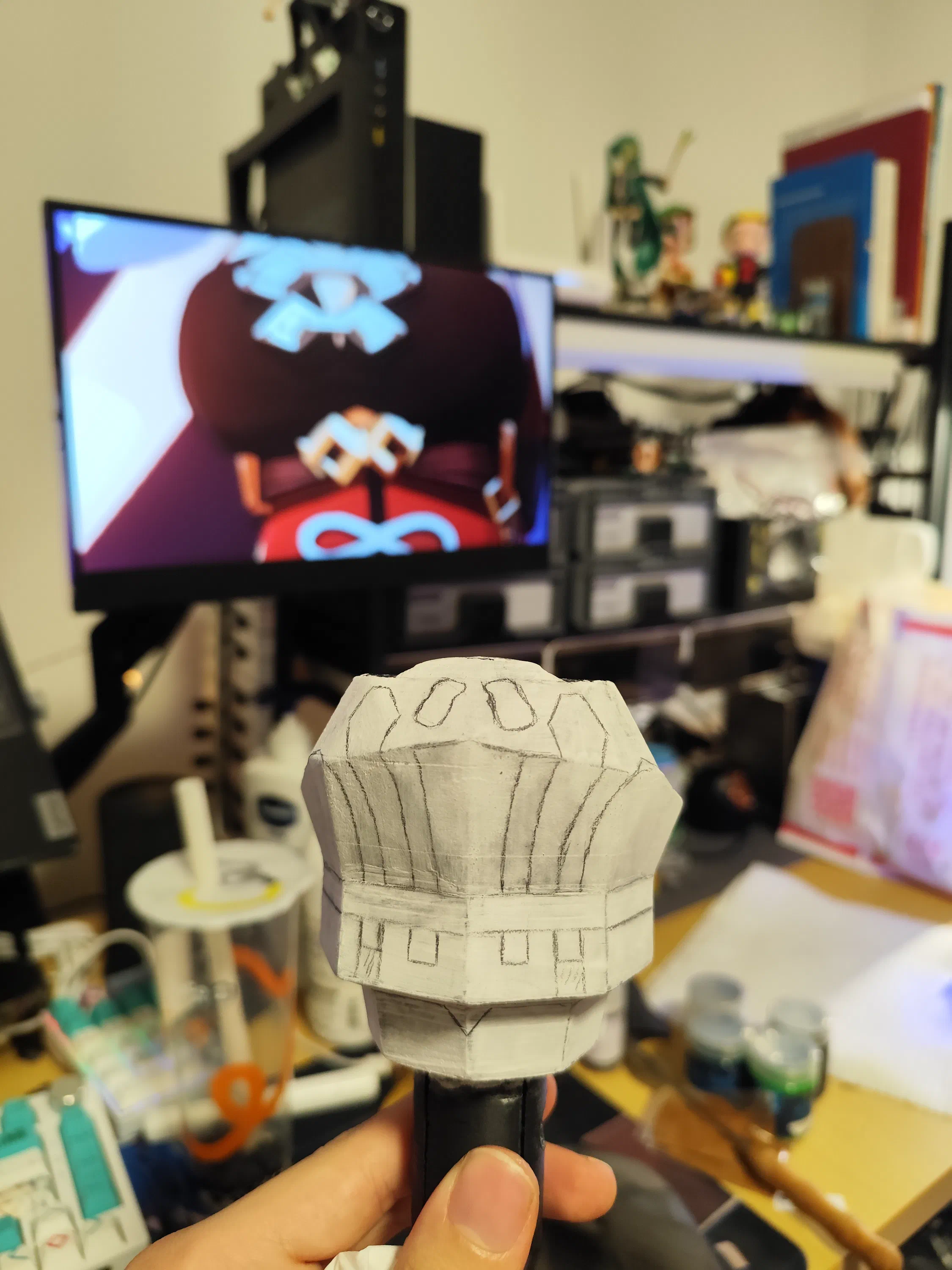
For large metallic and black-gradient regions, spray painting was far more efficient. Areas were masked and painted outdoors.
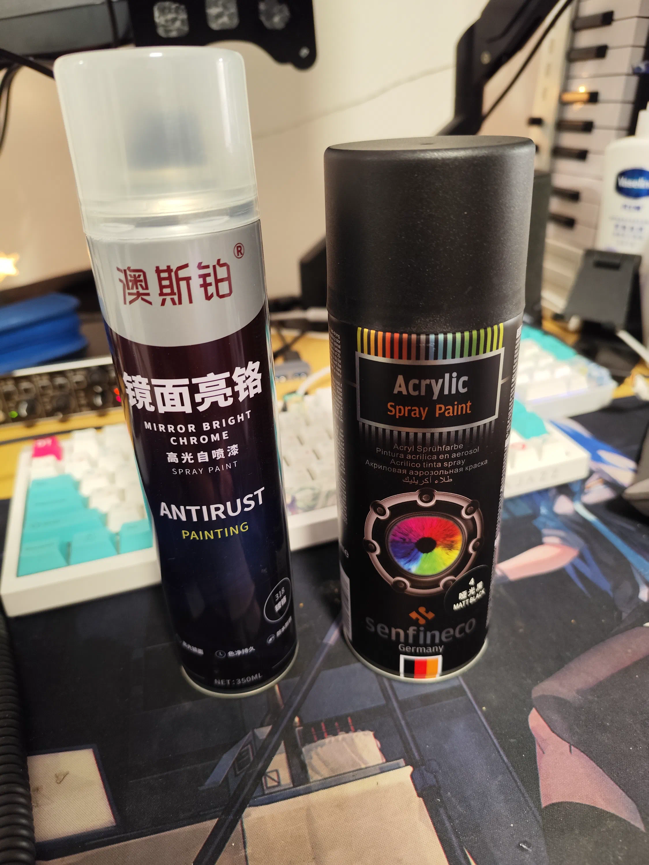
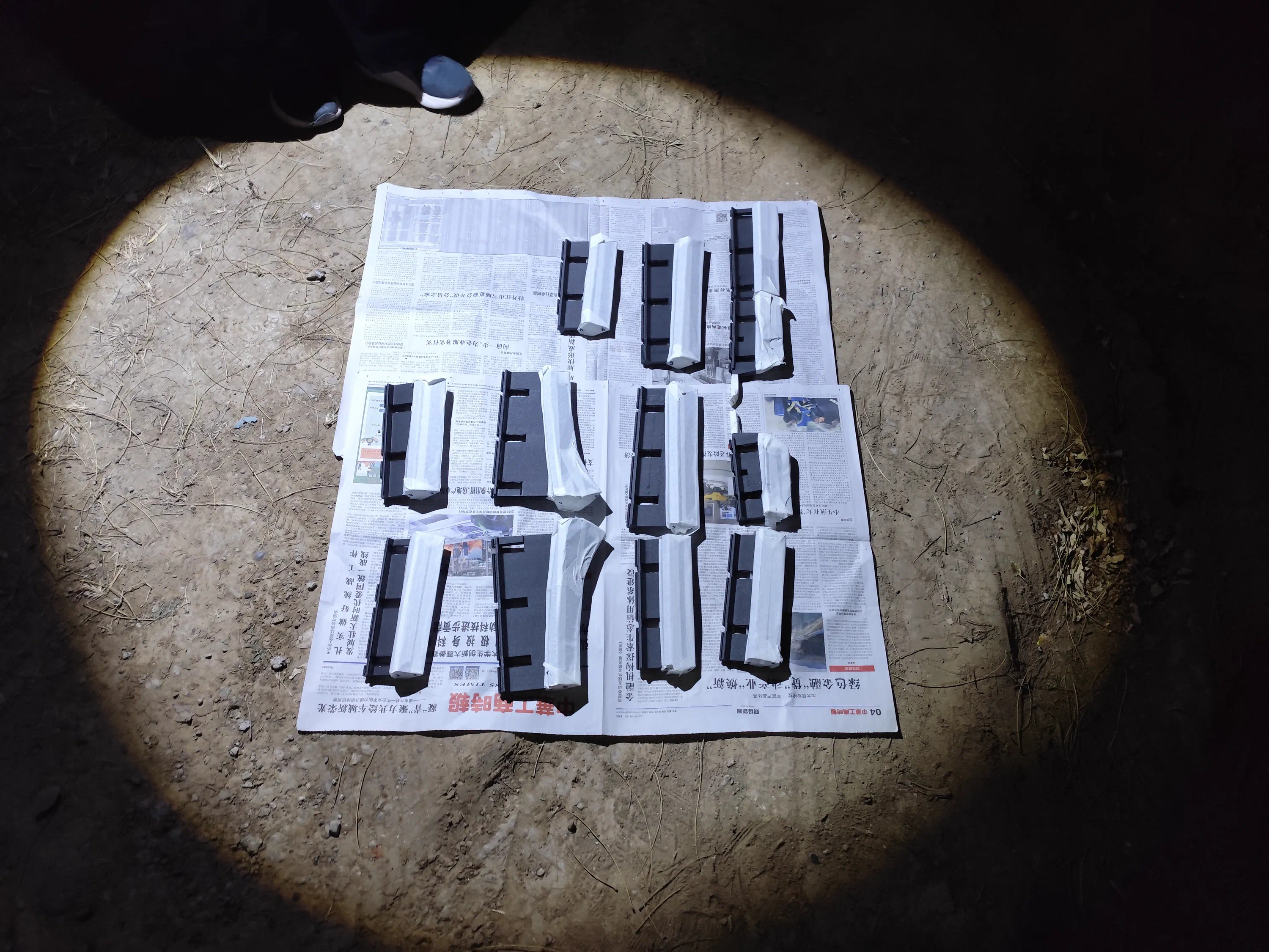
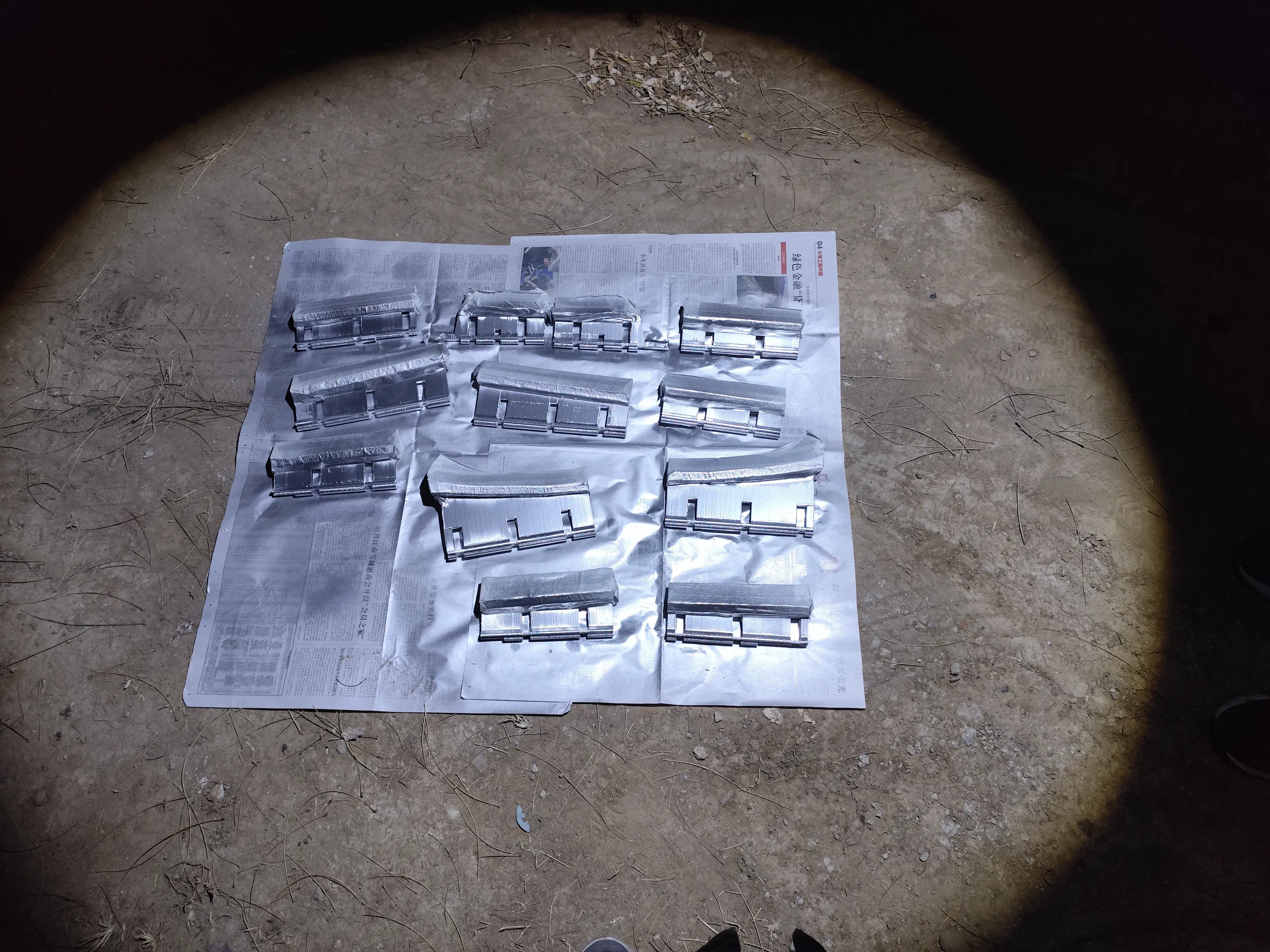
A reflective chrome pass was used to improve internal UV reflectance before top coats. Final acrylic clear coats added abrasion resistance and improved finish durability.
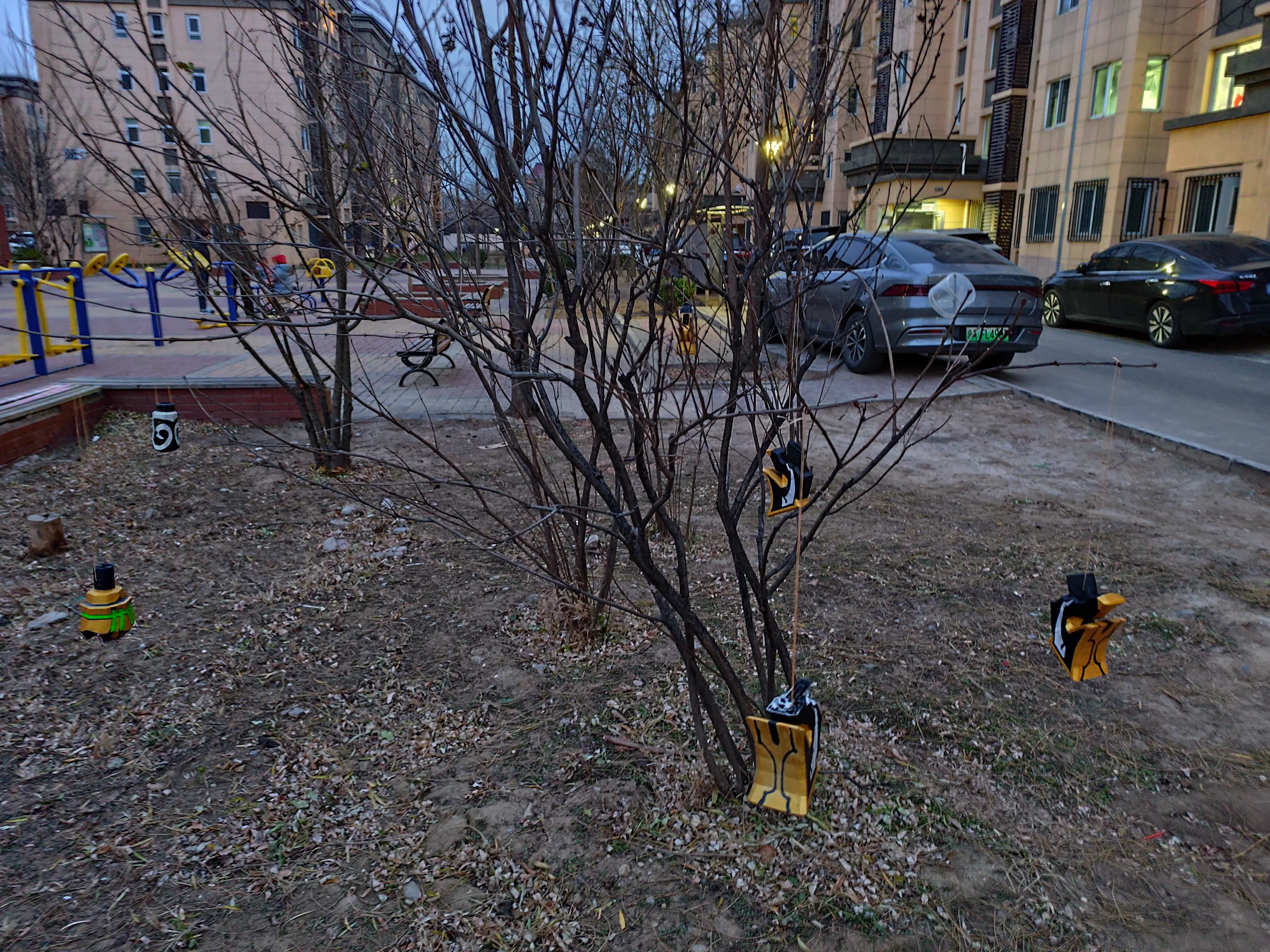
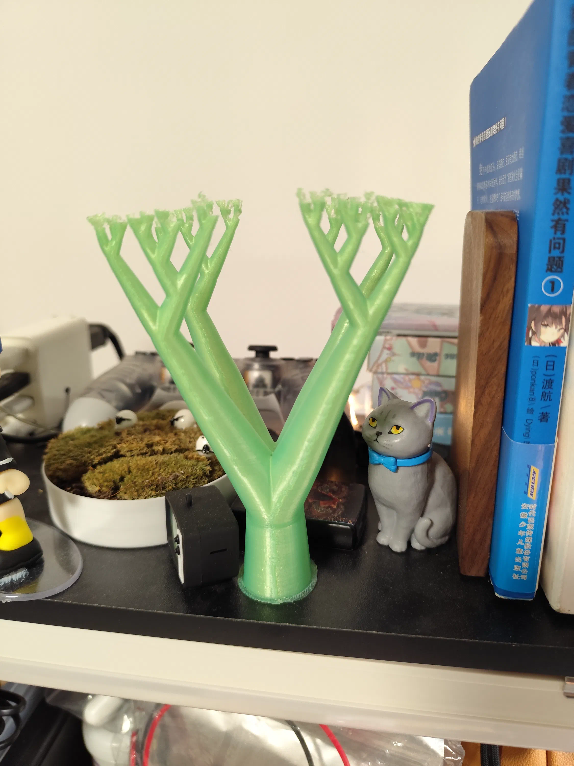
Conveniently, a tree ended up being the perfect rack between clear-coat passes. Accidental Genshin parts Christmas tree.
Showcase
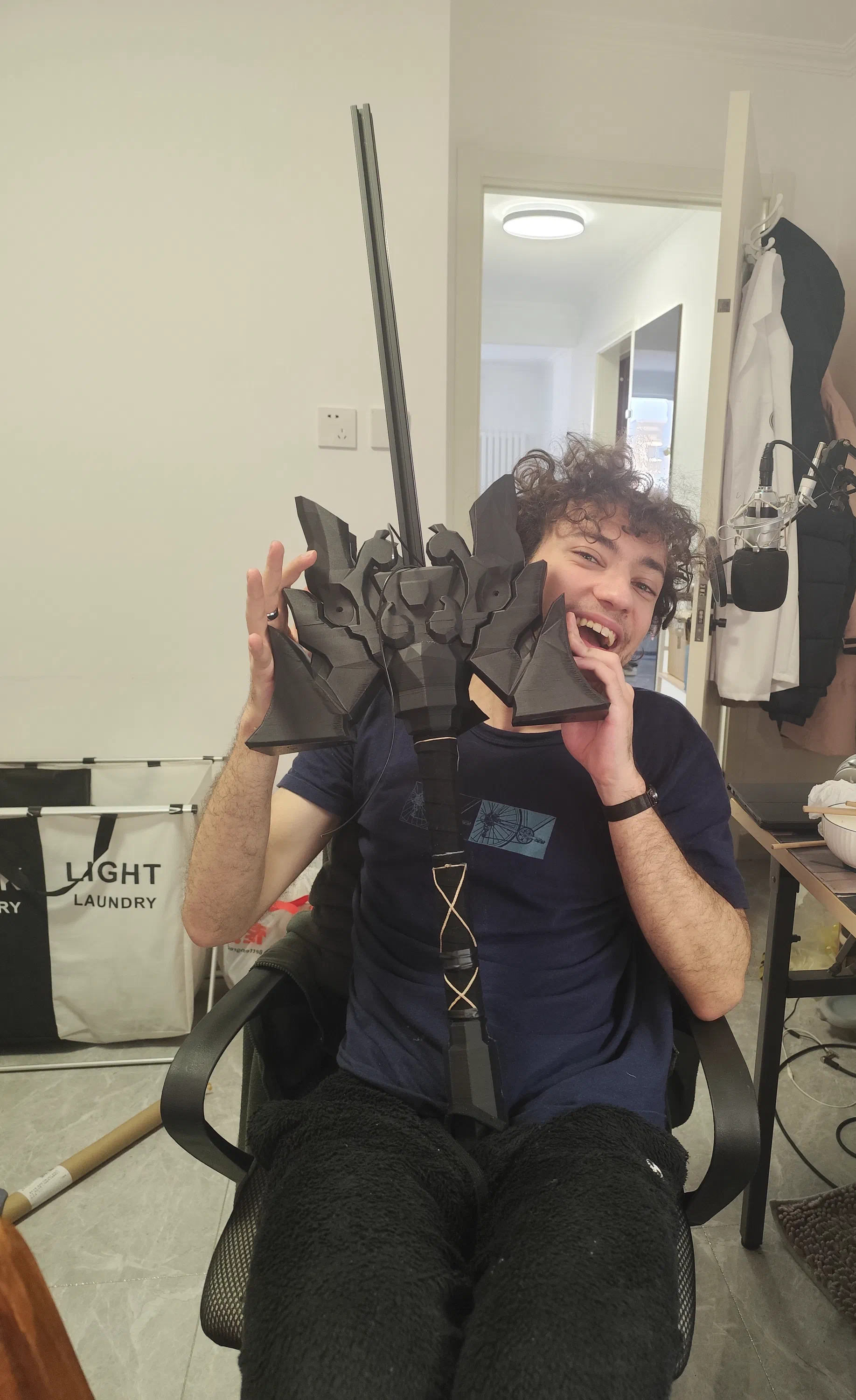
After nearly three months of work, the project was complete:
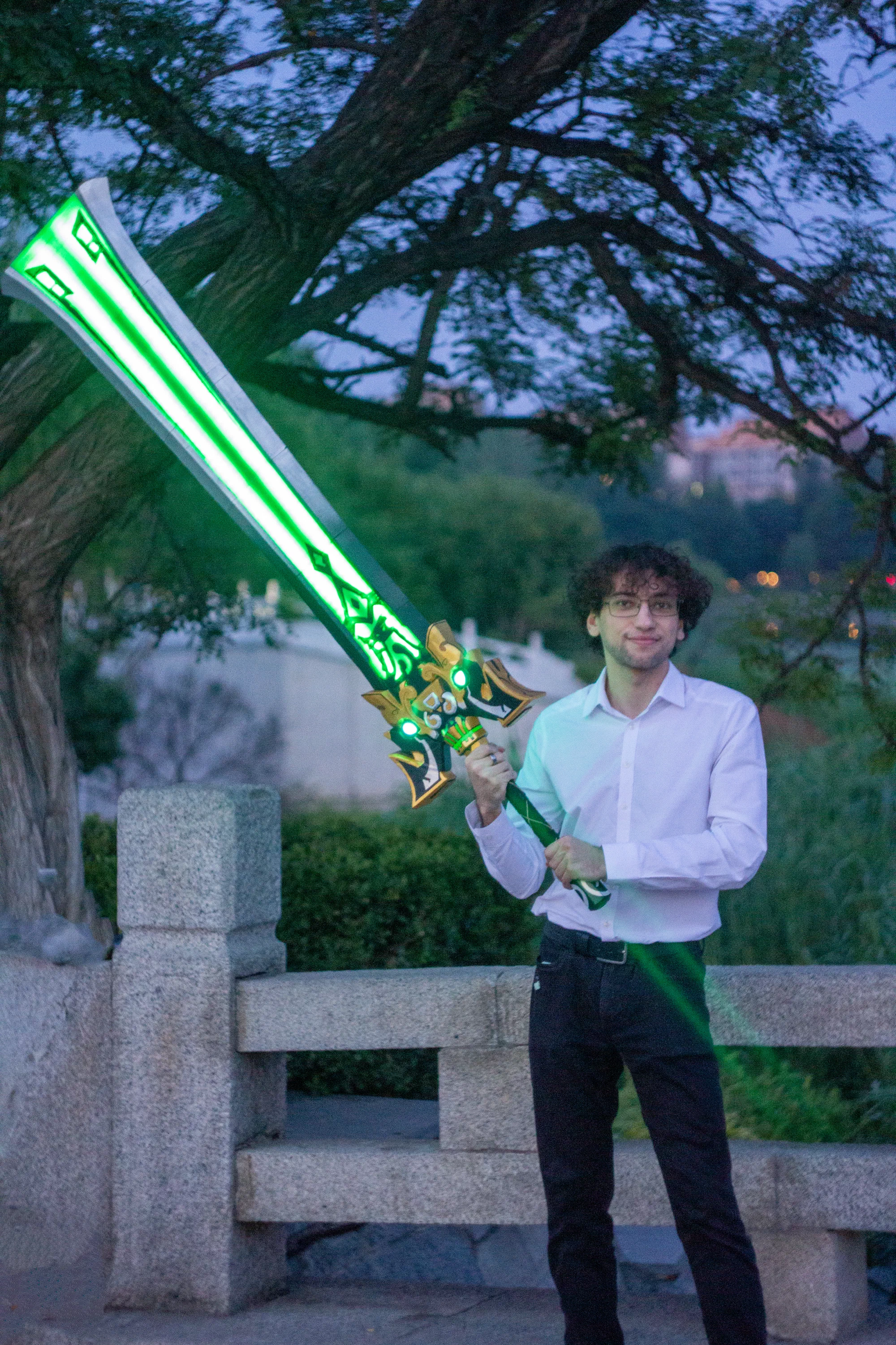

Followed, of course, by the obligatory full cosplay photoshoot: