
555 Timer Logic Probe
This is an old cross-post from Instructables, see the original here.
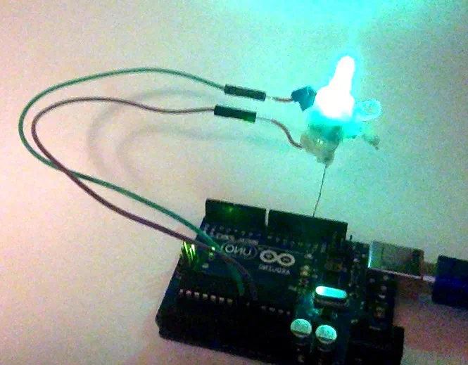
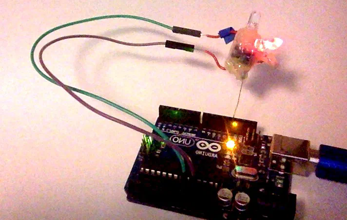
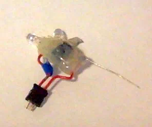
I got tired of haveing to get out my multimeter every time I had to measure a simple on or off, so I decided to build a probe. This probe uses a 555 Timer Chip as an inverting schemit trigger, sourcing and sinking two LEDs.
Step 1: How It Works
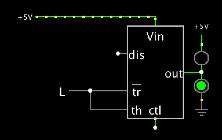
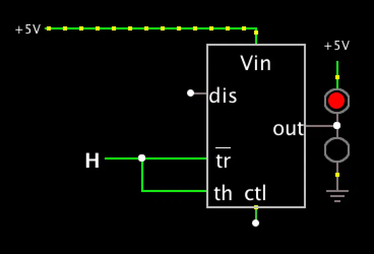
I’ve made a simulation of it, when the input is 1 or high the output gets set to 0 or low, which allows the red(1) led to get GND an light up, then when the in put is 0 or low the output is 1 or high which allows the green(0) led to get VCC and light up.
Step 2: What You Need
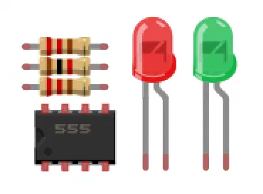
To build this you will need:
- 1x 555 Timer Chip Digikey
- 1x 1k Resistor Digikey
- 2x Resistors for LED’s (I used one 1k for the red led and none for the green led.) [Recommended values Digikey]
- 1x Red LED (for logic 1) Digikey
- 1x Green LED (for logic 0) Digikey
Step 3: Schematic
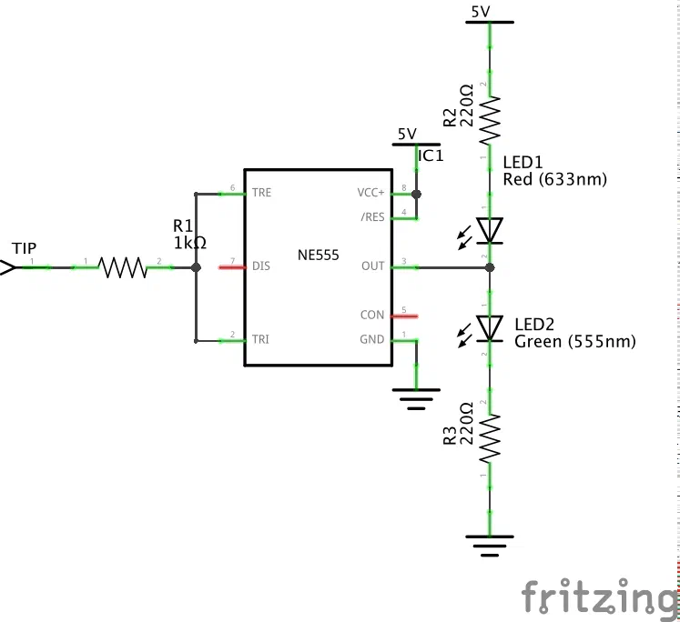
You can make it “dead bug” style like I did, or you could build it on a breadboard, or make a PCB. Just follow the diagram…
Step 4: Done!
Now you have your own logic probe built using a 555 timer!
It works pretty well, but when the probe tip is left “floating” (Not connected to anything) it will toggle somewhat randomly between 1 and 0, specially when you touch it. I attached a video of it measuring 1’s and 0’s on my Arduino with the blink scketch.