
Hologram Video Cropper - HoloCube Part 1
Contents
This is the first in a three part series on how I built a little HoloCube hologram video player and custom software dedicated to playing back hologram MMD concerts on this device. In this post I will cover the content-aware video cropper tool I built for the first video pre-processing step required to make this project come true.
Introduction to HoloCube & MMD Holograms
The HoloCube is a DIY mini hologram device originally created by the popular Chinese hobbyist 稚晖 (Peng ZhiHui) under the name HoloCubic; which I first stumbled upon on Bilibili.
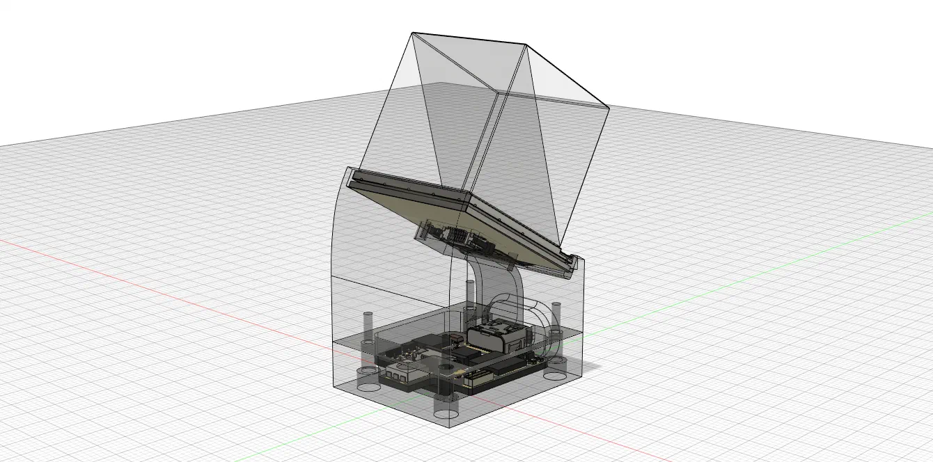
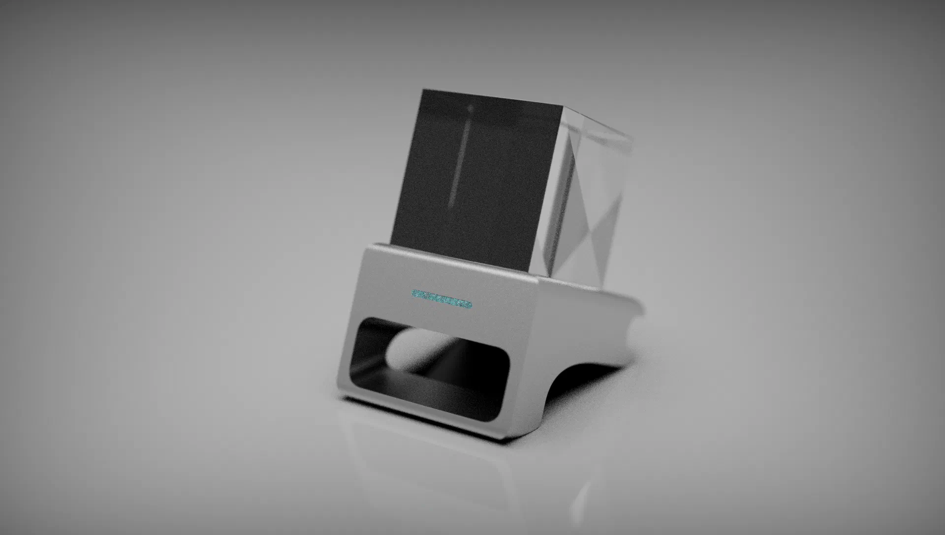
He combined an ESP32S3 with a 1.3" ST7789 240x240px TFT display, with a 1" beam-splitter prism to create the hologram illusion. I love this project and especially the form factor. However, it was missing a few key features in my view to be useful as a holo-concert viewer:
- Audio playback
- Full framerate video playback
- Video streaming over WiFi instead of only playing back videos from SD card
Below is the GitHub repository for his original implementation.
MikuMikuDance Holo Concerts
Miku Miku Dance is a free homebrew software created by 樋口M/ヒグチエム(Yu Higuchi) in 2008 to create dance animations as part of the VOCALOID promotion video project (VPVP). Thousands of fans have used it to create animations and hologram-ready videos using it. Just like in Hatsune Miku’s live MIKU EXPO concerts, a black background video is used so that when projected on a semi-transparent screen, a hologram is created. Below is an example with the song Anamanaguchi - Miku uploaded by Mekaio:
The Problem
As one can expect from the video above, there are several issues that means these videos cannot simply be cropped in the center to a square aspect ratio needed for the HoloCube. Here are the difficulties:
- Downscaling to 240x240 px while keeping the image sharp.
- Obtaining smooth camera panning to follow Miku as she walks around to the left and right of the frame, while making sure she is always perfectly framed.
- Dynamically zooming in and out to ensure everything is in frame, particularly when there are 2 or more VOCALOID dancers in the video.
With this in mind, I started designing a video processing algorithm to perform such content-aware crop work.
Implementing a Solution
I chose to favourite programming language; Go lang. This is because of it’s first-class concurrency primitives and the chan channel datatype, which allows me to easily pass live data concurrently between processing pipeline stages.
Let’s cover the pipeline stages I devised first, and then delve into the pipeline implementation itself later.
Stage 1: Convert to Grayscale
The first step is of course to read the video in and extract each frame, it is there frames which are passed along the pipeline stages. Then the first real processing step is to convert the video to grayscale as we don’t need the color data to perform cropping. This is the simplest and most straight forward part of the pipeline, and it’s done in just a few lines of code:
33func convertToMonochrome(img *image.RGBA) *image.Gray {
34    monoFrame := image.NewGray(img.Bounds())
35    draw.Draw(monoFrame, monoFrame.Bounds(), img, img.Bounds().Min, draw.Src)
36    return monoFrame
37}
38
39func convertGrayToRGBA(img *image.Gray) *image.RGBA {
40    rgbaFrame := image.NewRGBA(img.Bounds())
41    draw.Draw(rgbaFrame, rgbaFrame.Bounds(), img, img.Bounds().Min, draw.Src)
42    return rgbaFrame
43}
The result is, as expected, a grayscale video:
Stage 2: Convert to Bitmap via Otsu Threshold, Glob Components, Centroids & Bounding Boxes
The next challenge is to perform object detection to obtain a bounding box for the subjects without using computer vision AI (like YOLO) for example, but rather just traditional video DSP algorithms.
To achieve this, we first simplify the problem space even further by converting the grayscale video into a bitmap video (pixels are only fully on or fully off). In order to obtain this without dithering a simple threshold is used, so that all edges stay as sharp as they can be. A threshold operation will simply set all pixels above a certain value to 1, and all pixels below to 0. In order to ensure proper contrast so that even very dark parts (like Miku’s black boots) and light parts (like skin) are captured in the outline. This is where we can apply the Otsu algorithm.
Otsu’s method, fittingly developed by Nobuyuki Otsu, is a method that first calculates a histogram over the image and then finds the optimal split between the two main area peaks by calculating the inner-class variances. Below is a visualisation of this method from Wikipedia:

This is implemented with the Go code below:
 79func otsuThreshold(img *image.Gray) uint8 {
 80    // Calculate histogram
 81    histogram := make([]int, 256)
 82    totalPixels := float64(img.Bounds().Dx() * img.Bounds().Dy())
 83    for y := img.Bounds().Min.Y; y < img.Bounds().Max.Y; y++ {
 84        for x := img.Bounds().Min.X; x < img.Bounds().Max.X; x++ {
 85            intensity := img.GrayAt(x, y).Y
 86            histogram[intensity]++
 87        }
 88    }
 89
 90    // Normalize histogram
 91    var normalizedHistogram [256]float64
 92    for i := range histogram {
 93        normalizedHistogram[i] = float64(histogram[i]) / totalPixels
 94    }
 95
 96    // Calculate cumulative sum and cumulative mean
 97    var cumulativeSum [256]float64
 98    var cumulativeMean [256]float64
 99    cumulativeSum[0] = normalizedHistogram[0]
100    cumulativeMean[0] = 0
101    for i := 1; i < 256; i++ {
102        cumulativeSum[i] = cumulativeSum[i-1] + normalizedHistogram[i]
103        cumulativeMean[i] = cumulativeMean[i-1] + float64(i)*normalizedHistogram[i]
104    }
105
106    // Calculate between-class variance and find optimal threshold
107    var maxBetweenClassVariance float64
108    var optimalThreshold uint8
109    for t := 0; t < 256; t++ {
110        omega := cumulativeSum[t]
111        mu := cumulativeMean[t]
112        omega2 := 1 - omega
113        mu2 := (cumulativeMean[255] - mu) / omega2
114        betweenClassVariance := omega * omega2 * (mu - mu2) * (mu - mu2)
115        if betweenClassVariance > maxBetweenClassVariance {
116            maxBetweenClassVariance = betweenClassVariance
117            optimalThreshold = uint8(t)
118        }
119    }
120
121    return optimalThreshold
122}
123
124func applyThreshold(img *image.Gray, threshold uint8) *image.Gray {
125    binaryImg := image.NewGray(img.Bounds())
126    black := color.Gray{Y: 0}
127    white := color.Gray{Y: 255}
128
129    for y := img.Bounds().Min.Y; y < img.Bounds().Max.Y; y++ {
130        for x := img.Bounds().Min.X; x < img.Bounds().Max.X; x++ {
131            if img.GrayAt(x, y).Y < threshold {
132                binaryImg.SetGray(x, y, black)
133            } else {
134                binaryImg.SetGray(x, y, white)
135            }
136        }
137    }
138    return binaryImg
139}
After the threshold is applied, we now have a binary bitmap video. The next step is to label all connected components (adjacent pixels) with bounding boxes. This is done via a custom algorithm that utilised depth-first search (DFS) to label all connected components:
205// Connected component labeling algorithm
206func connectedComponentLabeling(binaryMap *image.Gray) (map[int]image.Rectangle, [][]int) {
207	labelMatrix := make([][]int, binaryMap.Bounds().Dy())
208	for i := range labelMatrix {
209		labelMatrix[i] = make([]int, binaryMap.Bounds().Dx())
210	}
211
212	boundingBoxes := make(map[int]image.Rectangle)
213
214	label := 1
215	for y := binaryMap.Bounds().Min.Y; y < binaryMap.Bounds().Max.Y; y++ {
216		for x := binaryMap.Bounds().Min.X; x < binaryMap.Bounds().Max.X; x++ {
217			if binaryMap.GrayAt(x, y).Y > 0 && labelMatrix[y][x] == 0 {
218				boundingBox := dfs(binaryMap, labelMatrix, x, y, label)
219				boundingBoxes[label] = boundingBox
220				label++
221			}
222		}
223	}
224
225	return boundingBoxes, labelMatrix
226}
227
228// Depth-first search to label connected components
229func dfs(binaryMap *image.Gray, labelMatrix [][]int, x, y, label int) image.Rectangle {
230    minX, minY, maxX, maxY := x, y, x, y
231
232    stack := []image.Point{{x, y}}
233    for len(stack) > 0 {
234        current := stack[len(stack)-1]
235        stack = stack[:len(stack)-1]
236
237        cx, cy := current.X, current.Y
238        labelMatrix[cy][cx] = label
239
240        if cx < minX {
241            minX = cx
242        }
243        if cx > maxX {
244            maxX = cx
245        }
246        if cy < minY {
247            minY = cy
248        }
249        if cy > maxY {
250            maxY = cy
251        }
252
253        // Check neighboring pixels
254        for dx := -1; dx <= 1; dx++ {
255            nx, ny := cx+dx, cy-1
256            if nx >= 0 && nx < binaryMap.Bounds().Dx() && ny >= 0 && ny < binaryMap.Bounds().Dy() {
257                if binaryMap.GrayAt(nx, ny).Y > 0 && labelMatrix[ny][nx] == 0 {
258                    stack = append(stack, image.Point{nx, ny})
259                }
260            }
261            ny = cy + 1
262            if nx >= 0 && nx < binaryMap.Bounds().Dx() && ny >= 0 && ny < binaryMap.Bounds().Dy() {
263                if binaryMap.GrayAt(nx, ny).Y > 0 && labelMatrix[ny][nx] == 0 {
264                    stack = append(stack, image.Point{nx, ny})
265                }
266            }
267        }
268        nx := cx - 1
269        ny := cy
270        if nx >= 0 && nx < binaryMap.Bounds().Dx() && ny >= 0 && ny < binaryMap.Bounds().Dy() {
271            if binaryMap.GrayAt(nx, ny).Y > 0 && labelMatrix[ny][nx] == 0 {
272                stack = append(stack, image.Point{nx, ny})
273            }
274        }
275        nx = cx + 1
276        if nx >= 0 && nx < binaryMap.Bounds().Dx() && ny >= 0 && ny < binaryMap.Bounds().Dy() {
277            if binaryMap.GrayAt(nx, ny).Y > 0 && labelMatrix[ny][nx] == 0 {
278                stack = append(stack, image.Point{nx, ny})
279            }
280        }
281    }
282
283    return image.Rect(minX, minY, maxX+1, maxY+1)
284}
Since there may be gaps in the islands created by threshold-ing the video, we need to then group adjacent bounding boxes within a certain radius into one master bounding box for our subject. This is done by simply combining bounding box bounds:
184// CombineBounds combines the bounds of all rectangles in the slice
185// that overlap with the given rectangle and removes them from the slice.
186func CombineBounds(rect image.Rectangle, rects []image.Rectangle, tol int) (combined image.Rectangle, remainingRects []image.Rectangle) {
187    // Initialize the combined rectangle with the rectangle passed as an argument
188    combined = rect
189
190    // Iterate over the rectangles in the slice
191    for _, r := range rects {
192        // Check if the current rectangle overlaps with the given rectangle
193        if ExpandRectangle(combined, tol).Overlaps(r) {
194            // Combine the bounds of overlapping rectangles
195            combined = combined.Union(r)
196        } else {
197            // Add the non-overlapping rectangle to the remaining rectangles slice
198            remainingRects = append(remainingRects, r)
199        }
200    }
201
202    return combined, remainingRects
203}
Finally, we have achieved bounding-box labelling of subjects in the video without using AI. However, one issue remains, the geometric center of the bounding box is not necessarily the visual center of our subject. Particulairly with Miku’s long twin-tail hair, which takes up more width than usual for a human-shaped subject; the geometric center does not accurately reflect the visual center.
To solve this, we use a centroid calculation algorithm, which performs a 2D weighted sum within the bounding box to find the mass center. Each white pixel effectively pulls the new center towards it, starting from the geometric center:
301func calculateCentroid(img *image.Gray, bbox image.Rectangle) image.Point {
302    totalX, totalY, count := 0, 0, 0
303    for y := bbox.Min.Y; y < bbox.Max.Y; y++ {
304        for x := bbox.Min.X; x < bbox.Max.X; x++ {
305            if img.GrayAt(x, y).Y == 255 { // white pixel
306                totalX += x
307                totalY += y
308                count++
309            }
310        }
311    }
312
313    if count > 0 {
314        return image.Point{totalX / count, totalY / count}
315    }
316
317    return image.Point{0, 0}
318}
It is this centroid center that we use for all further calculations down the pipeline. Below is the final output from this stage:
Here we can clearly see the bitmap video, a purple bounding box calculated for each connected component island, and the cyan subject bounding box and cyan centroid center.
Stage 3: Caculate Zoom and Pan & Interpolate using PID loops.
The last algorithmic step is to then use the detected subject bounding box and centroid center to control both the pan and zoom of the square crop camera. An active control loop is used with a PID each to control and smooth the zoom and pan. A PID class was implemented for this in pid_controller.go and it is initialised with some experimentally determined PID values which resulted in smooth camera motion:
19    pid = NewPIDController(0.1, 0.001*10e-10, 0.002*10e10, 0)
20    pidz = NewPIDController(0.2, 0.003*10e-10, 0.002*10e10, 0)
The PID target positions are set so that the centroid of the subjects (or average centroids for multiple subjects) is kept near the center of the square camera view:
103func calculatePanAdjustment(centroid image.Point, frameWidth int) int {
104    // Calculate how much you need to pan to keep the centroid in the center
105	panAdj := centroid.X - frameWidth/2
106
107	// smoothedPanAdj := ma.Add(panAdj)
108    pid.SetSetpoint(float64(panAdj))
109    smoothedPanAdj := pid.Update()
110    pid.SetDelta(pid.delta+smoothedPanAdj)
111
112    return int(pid.delta)
113}
114
115func calculateCropRect(centroid image.Point, frameWidth, cropWidth, panAdj int) image.Rectangle {
116	frameCtr := frameWidth/2
117	min := (cropWidth/2)-frameCtr
118	max := -min
119	panAdj = clamp(panAdj, min, max)
120
121	cropRect := image.Rect((frameCtr+panAdj)-cropWidth/2, 0, (frameCtr+panAdj)+cropWidth/2, cropWidth)
122
123	return cropRect
124}
Some additional safe-guards and custom logic is added to handle the zoom level, as well as some boundary conditions to avoid jerky motion if the bounding boxes computed from the previous step are invalid:
30            // Process the received image
31            bbox := mask.Bbox
32            centroid := calculateCentroid(mask.Mask, bbox)
33
34			panAdj := calculatePanAdjustment(centroid,mask.Image.Bounds().Dx())
35			bboxArea := bbox.Dx()*bbox.Dy()
36            frameArea := mask.Image.Bounds().Dx()*mask.Image.Bounds().Dy()
37            perCovered := float64(float64(bboxArea)/float64(frameArea))*100
38            bboxC := color.RGBA{0,0,255,255}
39            if perCovered < 0.1 {
40				// bounding box too small (< .1%), do not pan
41				panAdj = 0
42                bboxC = color.RGBA{255,0,255,255}
43			} else if perCovered > 75 {
44                // bounding box too big (> 80%), do not pan
45                panAdj = 0
46                bboxC = color.RGBA{255,0,255,255}
47            }
48            // fmt.Println(bboxArea, float64(float64(bboxArea)/float64(frameArea)))
49			cropRect := calculateCropRect(centroid,mask.Image.Bounds().Dx(),mask.Image.Bounds().Dy(),panAdj)
50
51            //? Experimental zoom out if width of bbox > cropRect
52            zoom := false
53            padding := int(cropRect.Dx()/8) // padding width of 1/10th of the crop rectangle width
54            perOut := float64(float64(bbox.Dx()) / float64(cropRect.Dx())) * 100
55            difOut := minBoxHDist(bbox, cropRect) //bbox.Dx()-cropRect.Dx()
56            difOut = clamp(difOut+padding, 0, cropRect.Dx()*5)
57            zoompx := 0
58            zoompx = difOut
59            pidz.SetSetpoint(float64(zoompx))
60            smoothedZoomAdj := pidz.Update()
61            pidz.SetDelta(pidz.delta+smoothedZoomAdj)
62
63            // Zoom
64            cropRect = ExpandRectangle(cropRect, clamp(int(pidz.delta), 0, cropRect.Dx()*5))
65            zoom = true
The final result is shown in the video below:
Where the blue rectangle shows the aggregated subjects bounding box, the red line and dot shows the subject centroid target, and the green bounding box shows the square camera view position (yellow showing the same but with zoom applied) returned from the PID controllers.
Notice here how smooth the movement of the green camera is, and how it accurately tracks Miku even when she walks to the left and right sides of the original 16:9 frame.
Since an absolute centroid center is calculated across all tracked subjects, this whole algorithm also works to track videos where multiple character’s are present. Below is the result from the song DiosP - Cendrillon, with the hologram-ready video from MMD Music:
Here the zoom part of the algorithm needs to do a lot more work in order to keep both Miku and KAITO in frame at the same time. Although it looks a little stuttery in this view, the final output after the last crop step is quite smooth.
Stage 4: Video Crop
The last stage is to actually apply the video zoom and crop calculated by the previous step and generate an output video. This is very straightforward:
21            // Process the received image
22			croppedImg := cropToBBox(mask.Image, mask.CBox)
23            //? Experimental zoom out and aspect ratio when bbox > cropRect
24            if mask.zoom {
25                // croppedImg = ResizeWithVerticalLetterbox(croppedImg, squareSize, squareSize)
26                croppedImg = ResizeRGBA(croppedImg, squareSize, squareSize)
27            }
At long last, we obtain our smoothly cropped square videos as the final output:
And the same goes for our multi-character videos, taking advantage of the zoom controller:
The PID controllers could probably do with some finer tuning, especially on the zoom side. But as most videos only feature one character anyway, I deemed this to be good enough.
Now we have a full content-aware square video cropping pipeline and tool which outputs videos ready for playback on the HoloCube’s square display. The next part of this series will cover more details about that.
Pipeline Setup Details
Lastly, before we finish off. I want to touch on some details of the pipeline implementation in Go lang, and just how easy it made to do such kind of concurrent processing.
We start setting up the pipeline by declaring all of the input/output image chennels between each step, as well as mutexes to ensure the read/write processes stay in sync between the different pipeline steps:
14var (
15	inputFrame 		*image.RGBA
16	inputFrameRW 	sync.Mutex
17
18	procFrameQueue1	chan *image.RGBA
19
20	grayFrame		*image.RGBA
21	grayFrameRW		sync.Mutex
22
23	procFrameQueue2	chan *ImageGrayMask
24
25	binaryFrame		*image.RGBA
26	binaryFrameRW	sync.Mutex
27
28	procFrameQueue3	chan *ImageGrayBoundMask
29
30	calcFrame		*image.RGBA
31	calcFrameRW		sync.Mutex
32
33	procFrameQueue4	chan *ImageCropMask
34
35	croppedFrame	*image.RGBA
36	croppedFrameRW	sync.Mutex
37
38
39	tempDirTinyVid  string
40    tempDirFrames   string
41)
Then, all we have to do to execute the pipeline is open the video and run all of the pipeline steps in concurrent go routines:
 86func startPipeline() {
 87	video, _ := vidio.NewVideo(filepath.Join(tempDirTinyVid,getBasenameWithoutExt(inputVideo)+".mp4"))
 88    tframes = video.Frames()
 89    cframes = 0
 90    if !playOnlyMode {
 91		bar = progressbar.Default(int64(tframes))
 92	}
 93	video.Close()
 94
 95	go readVideo()
 96	go grayscaleVideo()
 97	go binaryVideo()
 98	go calcVideo()
 99	go cropVideo()
100}
Everything is handled automatically. The receive and send loops inside of each pipeline step look like this:
10func grayscaleVideo() {
11	for {
12        select {
13        case img, ok := <-procFrameQueue1:
14            if !ok {
15                // Channel is closed
16                return
17            }
18
19            // Process the received image
20			maskFrame := convertToMonochrome(img)
21            if drawUI && !playOnlyMode {
22                grayFrameRW.Lock()
23                grayFrame = convertGrayToRGBA(maskFrame)
24                grayFrameRW.Unlock()
25            }
26			procFrameQueue2 <- &ImageGrayMask{Mask:maskFrame,Image:img}
27        }
28    }
29}
Where a select statement in a for loop is used to capture the incoming input frames in an event-driven manner, the mutex is locked/unlocked during the processing phase for UI display, and the output frame is sent to the queue channel of the next pipeline step.
Using such Go primitives, the pipeline processing became easy to implement rather than an asynchronous nightmare. As an added bonus, I included an Ebitten Engine based backend which can render an UI in real-time showing all of the processing steps as they happen:
All of the options for running the tool are documented and configurable via command line arguments:
$ ./1-1-Content-Aware-Video-Crop -h
Usage of ./1-1-Content-Aware-Video-Crop:
  -i string
        Input video or directory. Required.
  -o string
        Output directory (default current directory)
  -play
        Player only mode, do not write output. Just displays a preview of the result. (default false)
  -rt
        Whether to run in real-time (default false)
  -s int
        Size of square output video (default 256)
  -ui
        Whether to draw UI (default false)
More info can be found on my GitHub repo:
Next Steps
So there we have it, the first part of this three part saga to play MMD holographic concerts on the HoloCube. The next part will cover a custom video encoding format I developed in order to stream video and audio to the ESP32C3 MCU in a format that is optimally compressed while still being able to be decoded live with the limited processing power of this MCU.
I hope this was an interesting read and a little dive in the the world of classical video DSP. Any suggestions or improvements are more then welcome, just send me a PR on GitHub.